CM88Maintenace2x.PDF.pdf - 第109页
Page 1-17 CALIBRA TION 3Y3C-E-MMZ0A-A01-00 Pickup Position Calibration 2. Connect the connector A. 3. Remove the terminator B. 4. Connect the CCU connector to B. A 3Y3C-155P 3Y3C-156P B 3Y3C-157P B T o the next page
Page 1-16
3Y3C-E-MMZ0A-A01-00
Pickup Position Calibration
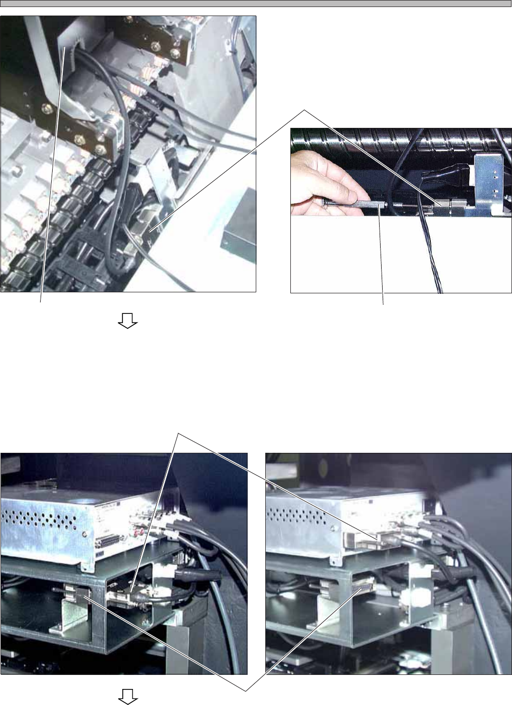
3. Connect the camera jig with the sig-
nal wire of the CCU.
∗ Insert the connector, then tighten the screws
with the driver.
4. Wire the CCU.
∗ Before wiring, make sure that the power supply
switch of the CCU is OFF.
1. Remove the signal wire connector from the
terminator, then connect it to the CCU.
Connector
Camera Jig
Driver
Terminator
3Y3C-152P
To the next page
3Y3C-153P
3Y3C-147P
3Y3C-154P
Connector
Page 1-17
CALIBRATION
3Y3C-E-MMZ0A-A01-00
Pickup Position Calibration
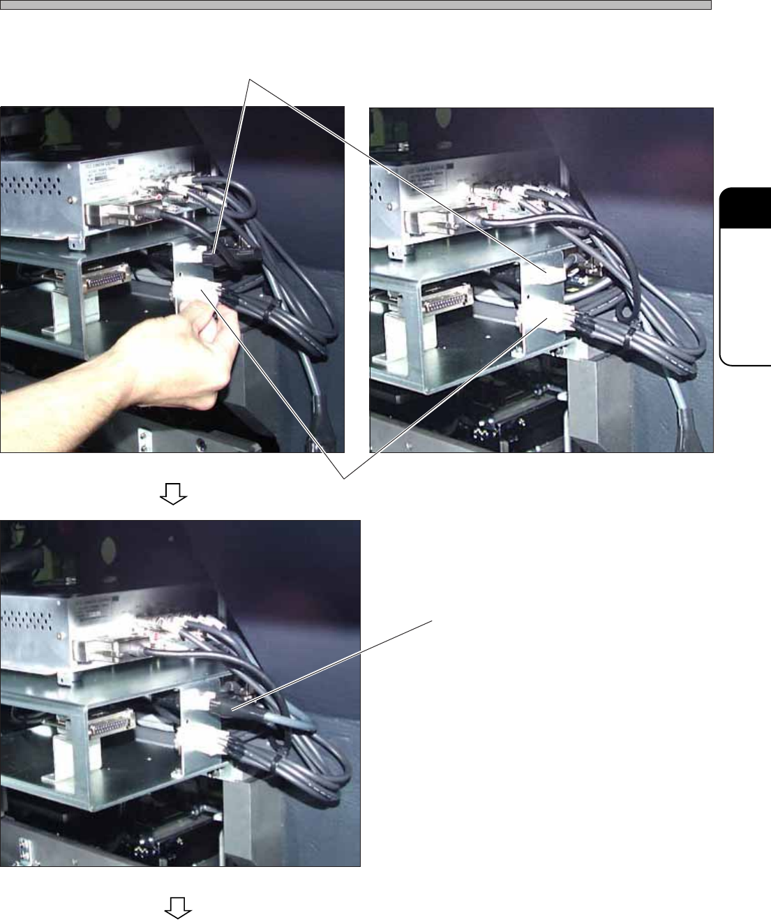
2. Connect the connector A.
3. Remove the terminator B.
4. Connect the CCU connector to B.
A
3Y3C-155P
3Y3C-156P
B
3Y3C-157P
B
To the next page
Page 1-18
Pickup Position Calibration
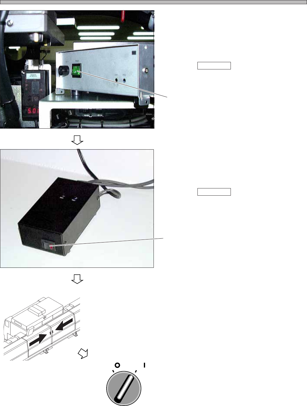
5. Turn ON the power supply.
1. Turn ON the power supply of the CCU.
∗ However, the power is not supplied from the
machine.
When Teach start is pressed, the power is
supplied from the machine.
2. Turn ON the power supply of the power supply
box.
∗ However, the power is not supplied from the
machine.
When Teach start is pressed, the power is
supplied from the machine.
6. Close the rear center safety cover.
7. Turn ON the servo switch.
3Y3C-E-MMZ0A-A01-00
Switch
3Y3C-158P
3Y3C-159P
OFF ( )
ON ( )
SERVO
Switch
3Y3C-AG01