CM88Maintenace2x.PDF.pdf - 第61页
Page 3-33 SOLUTIONS FOR ERROR 3 Check and Solutions ∗ The description is for the CPU BOX for CM88S-M. 3Y3C-E-MMD03-A03-01 3-2-28 Counter Error 1. Setting the board (MCMAER) If wrong setting of CPU box front side board (M…
Page 3-32
3Y3C-E-MMD03-A03-02
Check and Solutions
3. Checking the state of theta-axis board
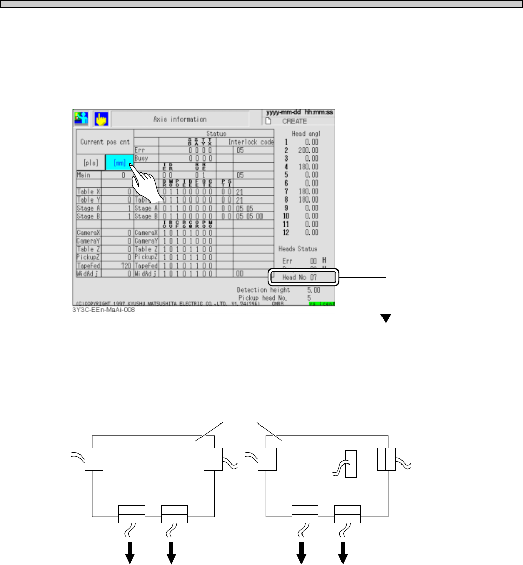
1.Check “Head No. ∗ ∗ ” displayed at the lower right on the “Axis information” screen after “Machine
adjust.”
(See “Stop history in 5-2 Stop information” in Operating Manual (for Operators), for checking the
state.)
The head of No. ∗ ∗ is the one with error
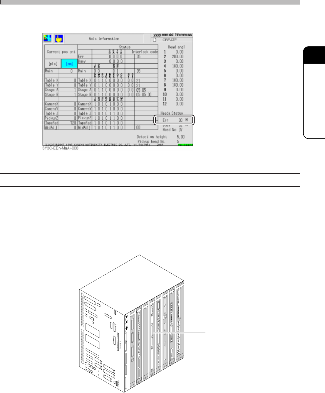
2.Check the connection on the upper theta axis board connector with covers removed. If a loose
connector is found, connect it properly, and reset the cover.
3Y3C-117E
θ-axis board
Head Head Head Head
×5
×1
E.g.) For number 7 head, it is described “Head No. 07”
Page 3-33
SOLUTIONS FOR ERROR
3
Check and Solutions
∗ The description is for the CPU BOX for CM88S-M.
3Y3C-E-MMD03-A03-01
3-2-28 Counter Error
1. Setting the board (MCMAER)
If wrong setting of CPU box front side board (MCMAER) is found, set it properly.
2. Connecting connections
Check the connection of CPU box board (MCMAER) connector, and reset it if the connection is
loose.
Board (MCMAER)
CN01
CN25
CN00
CN13
CN20
CN51
CN27
CN5
SW1
CN4
CN19
CN23
CN24
CN50
CN26
CN14
CN28
CN29
CN30
CN31
CN32
CN33
CN34
NR1
NR2
CN18
CN8
CN7
CN
TEST 3
CNTEST 4
CNTEST 1
CNTEST 2
CN2
CN1
CN21
CN22CN17
CN11
CN12
CN9
CN10
CN15
CN1
CN2
CN3
OPT1OPT2OPT3OPT4OPT5
OPT6OPT7
CN1
CN2
CN3
CN1
CN2
CN3
CN4
CN4
CN2
CN1
CN3
CN5
CN
10
CN
9
CN
7
CN
6
CN1CN2
CN3
CN4
CN5
CN6
CN2
CN3
CN4
CN5
CN
8
N
C
G
N
D
1
1
2
V
G
N
D
2
G
N
D
1
+
5
V
+
2
4
V
-
1
2
V
+
1
2
V
+
5
V
G
N
D
3
+
2
4
V
-
1
2
V
+
1
2
V
G
N
D
2
G
N
D
1
+
5
V
C
N
C
G
N
D
3
+
2
4
V
-
1
2
V
G
N
D
2
+
1
2
V
G
N
D
1
+
5
V
N
C
L
N
F
G
E
C
5
5
C
A
N
F
M
0
C
K
C
M
M
7
C
A
M
C
M
A
E
R
P
R
M
7
E
Q
E
L
L
Z
E
A
S
C
M
W
E
E
P
U
0
2
E
1
G
N
D
+
5
V
N
C
G
N
D
1
G
N
D
+
5
V
3Y3C-109E
3.If the trouble is not found, check the error code, “Err ∗ ∗ H” displayed at the lower right on the
“Axis information” screen, and make contact with us.
Page 3-34
Check and Solutions
3Y3C-E-MMD03-A03-01
3-2-29 Feedback Error
Positioning Time Over
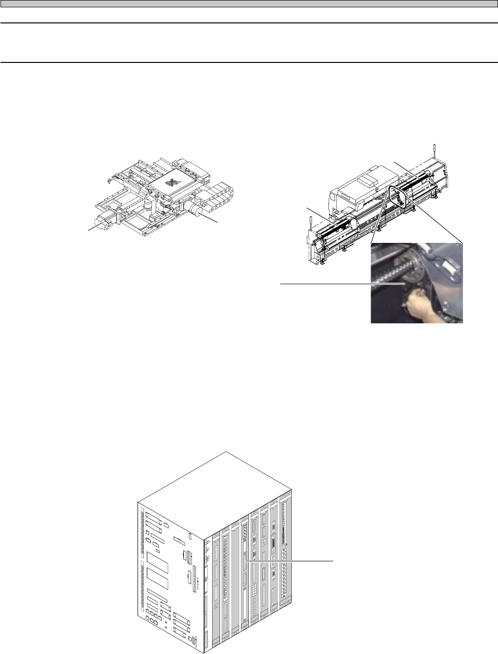
1. Lubricating the axis with error
Check the smooth movement of axis indicated as the error by hand (rotate the timing belt for the
stage axis). If it is hard to move the axis on the way, lubricate the ball screw.
2. Setting the state of board (MCMAER) and connecting connections
If the disconnection or wrong setting of CPU box front side board (MCMAER) is found, connect and
set them properly.
Table Y-axis
A stage axis
Timing belt
Table X-axis
B stage axis
3Y3C-098P
07JHC2AA
3Y3C-AK01
Board (MCMAER)
CN01
CN25
CN00
CN13
CN20
CN51
CN27
CN5
SW1
CN4
CN19
CN23
CN24
CN50
CN26
CN14
CN28
CN29
CN30
CN31
CN32
CN33
CN34
NR1
NR2
CN18
CN8
CN7
CN
TEST 3
CNTEST 4
CNTEST 1
CNTEST 2
CN2
CN1
CN21
CN22CN17
CN11
CN12
CN9
CN10
CN15
CN1
CN2
CN3
OPT1OPT2OPT3OPT4OPT5
OPT6OPT7
CN1
CN2
CN3
CN1
CN2
CN3
CN4
CN4
CN2
CN1
CN3
CN5
CN
10
CN
9
CN
7
CN
6
CN1CN2
CN3
CN4
CN5
CN6
CN2
CN3
CN4
CN5
CN
8
NC
GND1
12V
GND2
GND1
+5V
+24V
-12V
+12V
+5V
GND3
+24V
-12V
+12V
GND2
GND1
+5VC
NC
GND3
+24V
-12V
GND2
+12V
GND1
+5V
NC
L
N
FG
EC55CA
NFM0CK CMM7CA
MCMAER
PRM7EQ
ELLZEA
SCMWEE
PU02E1
GND
+5V
NC
GND1
GND
+5V
3Y3C-109E
∗ The description is for the CPU BOX for CM88S-M.