CM88Maintenace2x.PDF.pdf - 第55页
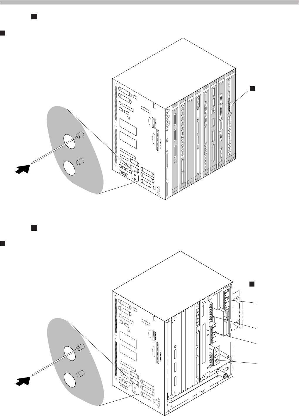
Page 3-27 SOLUTIONS FOR ERROR 3 3Y3C-E-MMD03-A03-01 Check and Solutions 3-2-23 Head Number Mismatch 1. Checking the state of head recognition encoder Check for looseness of fixing the head recognition encoder as follows.…
Page 3-26
3Y3C-E-MMD03-A03-01
Check and Solutions
CM88S-M/M1, CM88C-D
C
N
0
1
C
N
2
5
C
N
0
0
C
N
1
3
C
N
2
0
C
N
5
1
C
N
2
7
C
N
5
S
W
1
C
N
4
C
N
1
9
C
N
2
3
C
N
2
4
C
N
5
0
C
N
2
6
C
N
1
4
C
N
2
8
C
N
2
9
C
N
3
0
C
N
3
1
C
N
3
2
C
N
3
3
C
N
3
4
N
R
1
N
R
2
C
N
1
8
C
N
8
C
N
7
C
N
T
E
S
T
3
C
N
T
E
S
T
4
CNTEST 1
CNTEST 2
CN2
CN1
CN21
CN22CN17
CN11
CN12
CN9
CN10
CN15
CN1
CN2
CN3
OPT1OPT2OPT3OPT4OPT5
OPT6OPT7
CN1
CN2
CN3
CN1
CN2
CN3
CN4
CN4
CN2
CN1
CN3
CN5
CN
10
CN
9
CN
7
CN
6
CN1CN2
CN3
CN4
CN5
CN6
CN2
CN3
CN4
CN5
CN
8
NC
GND1
12V
GND2
GND1
+5V
+24V
-12V
+12V
+5V
GND3
+24V
-12V
+12V
GND2
GND1
+5VC
NC
GND3
+24V
-12V
GND2
+12V
GND1
+5V
NC
L
N
FG
EC55C
A
N
FM
0C
K
C
M
M
7CA
M
CM
AE
R
PR
M
7EQ
E
LLZEA
SC
M
W
EE
PU
02E
1
GND
+5V
NC
GND1
GND
+5V
Circuit protector
Upper (NR2) : DC24V (Output system)
Lower (NR1) : DC12V (Input system)
3Y3C-109E
3Y3C-110E
Checking pin
Board (PU02E1)
Circuit protector
Upper (NR2) : DC24V (Output system)
Lower (NR1) : DC12V (Input system)
4G3C-002E
3Y3C-110E
Power supply for
specified voltage
C
N
0
1
CN01
C
N
2
5
CN25
C
N
0
0
CN00
C
N
1
3
CN13
C
N
2
0
CN20
C
N
5
1
CN51
C
N
2
7
CN27
C
N
5
CN5
S
W
1
SW1
C
N
4
CN4
C
N
1
9
CN19
C
N
2
3
CN23
C
N
2
4
CN24
C
N
5
0
CN50
C
N
2
6
CN26
C
N
1
4
CN14
C
N
2
8
CN28
C
N
2
9
CN29
C
N
3
0
CN30
C
N
3
1
CN31
C
N
3
2
CN32
C
N
3
3
CN33
C
N
3
4
CN34
N
R
1
NR1
N
R
2
NR2
C
N
1
8
CN18
C
N
8
CN8
C
N
7
CN7
C
N
CN
T
E
S
T
3
TEST 3
C
N
T
E
S
T
4
CNTEST 4
CNTEST 1
CNTEST 1
CNTEST 2
CNTEST 2
CN2
CN2
CN1
CN1
P100E-24
P50E-12
P100E-5
P15E-12
CM88S-MU
Page 3-27
SOLUTIONS FOR ERROR
3
3Y3C-E-MMD03-A03-01
Check and Solutions
3-2-23 Head Number Mismatch
1. Checking the state of head recognition encoder
Check for looseness of fixing the head recognition encoder as follows.
If looseness is found, make contact with us for changing them.
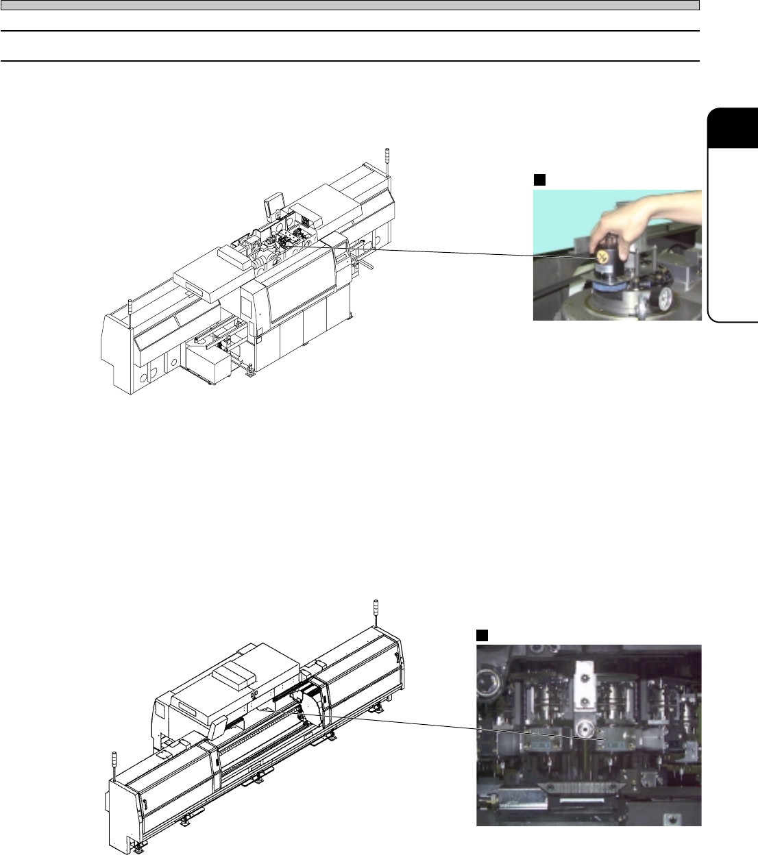
Encoder
Pickup head No.
2. Checking the state of head recognition encoder by the axis information
Display the “Axis information” screen after “Machine adjust.”
Check “Pickup head No. ∗ ∗” (the No. in the software) displayed at the lower right on the screen
and actual pickup head No. (the No. of head recognition encoder). If values are not the same one,
the encoder may have trouble. Make contact with us for changing.
4G3C-AD01
3Y3C-093P
3Y3C-AI01
3Y3C-094P
Page 3-28
3Y3C-E-MMD03-A03-01
Check and Solutions
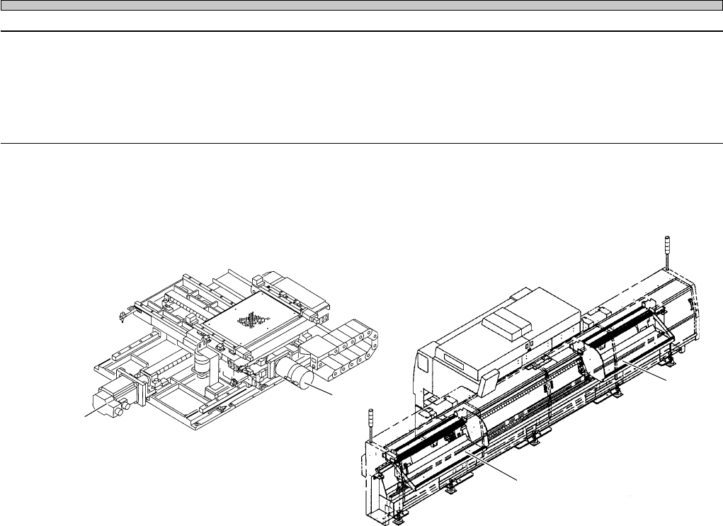
3-2-24 Table X-axis Motion Partial
Table Y-axis Motion Partial
A Stage-axis Motion Partial
B Stage-axis Motion Partial
1. Cleaning and applying grease to the ball screw
Clean and apply grease to each axis, according to its condition. When any trouble is found, restart
the operation. If the error occurs after restart, as it may be the error of axis, make contact with us.
Table X-axis
A stage axis
Table Y-axis
B stage axis
07JHC2AA
3Y3C-AK01