CM88Maintenace2x.PDF.pdf - 第93页
Page 1-1 3Y3C-E-MMZ0A-A01-00 Appendix MOUNTING/PICKUP MOUNTING/PICKUP POSITION CALIBRATION POSITION CALIBRATION (OPTION) (OPTION) T able of Contents 1-1 Mounting Position Calibration .....................................…

Page 4
3Y3C-E-MMA0Y-A01-07
O
Oil cooling box error..............3-4, 3-5, 3-9, 3-40
Other errors protection...................................3-38
Outer load arrangement (CM88C-D) .............3-47
Outer load arrangement (CM88S-M) .............3-45
Outer load arrangement (CM88S-M1) ...........3-46
Outer load arrangement (CM88S-MU)...........3-48
Output check after errors ...............................3-53
Overcurrent protection ...................................3-38
Overheat protection .......................................3-38
Overload protection........................................3-38
Overspeed protection.....................................3-38
Overvoltage protection...................................3-38
P
Parameter error......................................3-9, 3-37
PCB recognition error ............................3-5, 3-21
PCB transport error..........................................3-5
Pick Z-axis motor driver err......................3-3, 3-7
Pickup head interlock.......................................3-6
Pickup height motor error...............................3-29
Pickup height motor error.................................3-7
Pickup pos head descend................................3-4
Pickup pos head descend (pickup head interlock) ..
3-15
Pin positioning error .........................................3-5
Plane figure of main body 1 ...........................3-41
Plane figure of main body 2 ...........................3-42
Positioning overdeviation protection ..............3-38
Positioning time over......................................3-34
Positioning time over error ...............................3-8
Power box over heat...............3-4, 3-5, 3-9, 3-19
Power OFF by the failure, etc. during last prod ..
3-9
Production end signal detected..............3-3, 3-15
PRU power supply fault .........................3-6, 3-25
PT communication error...................................3-2
PT communication time-out .............................3-2
PT recog data not exist ....................................3-2
R
R width adjust motor driver error......................3-7
Rear conveyor......................................3-49, 3-50
Rear cover open stop...............3-3, 3-5, 3-6, 3-8
Receiving parameter error protection ............3-38
Recog communication error...................3-5, 3-22
Recognition time out error................................3-5
Regenerative error protection ........................3-38
S
Safety cover open ..........................................3-13
Safety relay (AST cover SW) wrong circuit ......3-4
Safety relay (BST cover SW) wrong circuit ......3-4
Safety relay (emergency stop SW) wrong circuit..
3-4
Safety relay (front, center, rear SW) wrong circuit ..
3-4
Servo switch OFF...........................3-3, 3-6, 3-11
Solenoid arrangement....................................3-44
Solenoid list (VL) ............................................3-51
Stage dividing...................................................3-9
Stage exchanging ............................................3-9
Stage interference............................................3-3
Stage interlock .................................................3-8
Stage interlock (stage interference) ...............3-17
Stage jointing ...................................................3-9
Stage position detection sensor error ..............3-4
Sub-conveyor adjust error................................3-5
System error protection..................................3-38
System interlock.....................................3-9, 3-39
T
Table X-axis motion partial .....................3-7, 3-28
Table Y-axis motion partial .....................3-7, 3-28
Table Z-axis (+) overrun ...................................3-7
Table Z-axis (–) overrun ...................................3-7
Table Z-axis motion partial .....................3-7, 3-29
Table Z-axis motor driver error .........................3-7
Tape feed changeover driver error ...................3-7
Tape feed interlock ...................................3-6, 3-8
Tape feed ROD descend..................................3-3
Tape feed Rod descend (adhesive tape feed interlock) .
3-15
Tape feeder miss rate over...............................3-5
The feeder set error .........................................3-5
The input and output check of machine .........3-52
Time over fault .......................................3-8, 3-36
V
Vacuum pump over heat ................3-4, 3-6, 3-18
Voltage error...........................................3-9, 3-37
W
Wait for chip recognition...................................3-9
Wait for post process .......................................3-9
Wait for pre process .........................................3-9
Wait for replenish complete..............................3-9
Width adjust error...........................3-6, 3-9, 3-24
Width adjust start chk err .................................3-6

Page 1-1
3Y3C-E-MMZ0A-A01-00
Appendix
MOUNTING/PICKUP
MOUNTING/PICKUP
POSITION CALIBRATION
POSITION CALIBRATION
(OPTION)
(OPTION)
Table of Contents
1-1 Mounting Position Calibration.............................................................. 1-2
1-2 Pickup Position Calibration ................................................................. 1-11
Mounting/Pickup Position Calibration
Background and Outline of “Mounting Position Calibration”
• Background
The accuracy of the measuring instruments are calibrated regularly. The system that calibrates
the accuracy of the mounters regularly is also manufactured.
To maintain the accuracy and quality durability, use this system.
• Outline
CM88S(C) can be equipped with five nozzles at each head. Accuracy will be improved by correct-
ing each angle of each nozzle. Nozzles are specified, dummy chips are mounted, the accuracy is
measured by the board recognition camera and the correction value will be input automatically so
that the accuracy will improve. The measurement result is output from the printer automatically.
If this procedure is performed twice, the first data will be the current mounting accuracy and the
second data will be the one corrected this time.
Background and Outline of “Pickup Position Calibration”
• Background
The correct pickup posture will improve accuracy and reduce the pickup errors. To calibrate the
nozzle position accuracy regularly, this system is manufactured.
• Outline
To pick up minute chips, it is required to be very accurate.
So, the accuracy will be calibrated in the following procedure so that the chip will be picked up at
its center. The accuracy of 0603 and 1005 nozzles is recognized by the camera for each head, it
is automatically fed back and the accuracy of the 12 heads is equalized.
Page 1-2
3Y3C-E-MMZ0A-A01-00
1-1 Mounting Position Calibration
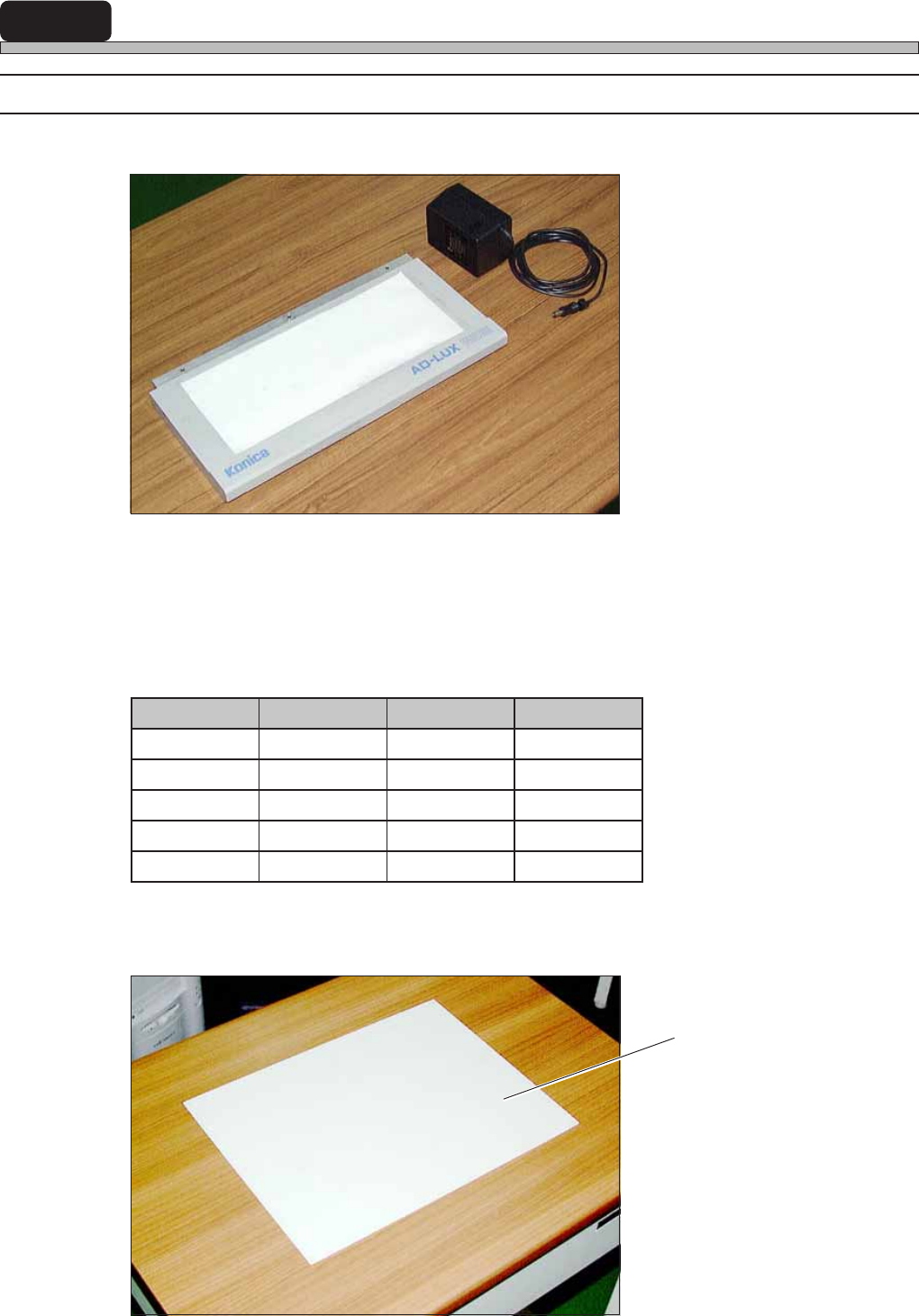
1-1-1 Preparation
1. Light Source
2. Extension Cord
Prepare this for yourself.
3. Data (Floppy Disk or PT) and Chips
Main tact time = 0.1 s
4. Exclusively Reserved Board
Stick a double-sided tape on the mounting side.
elzzoN pihC feR GAM
5001R5001552
8061C8061152
5212C5212152
6123C6123152
3060C3060552
Exclusively Reserved Board
3Y3C-135P
3Y3C-134P
3Y3C-119TE