3OM-1751-002w_G5S.pdf - 第102页
3OM-1751 1-48 1303-001 [Save] button When this button is pressed, the teaching results are saved. • Glass Jig PCB JG-0166 (PEC Recognition Calibration Jig) For the "PEC Recognition Camera & Beam Of fset" te…
3OM-1751
1-471303-001
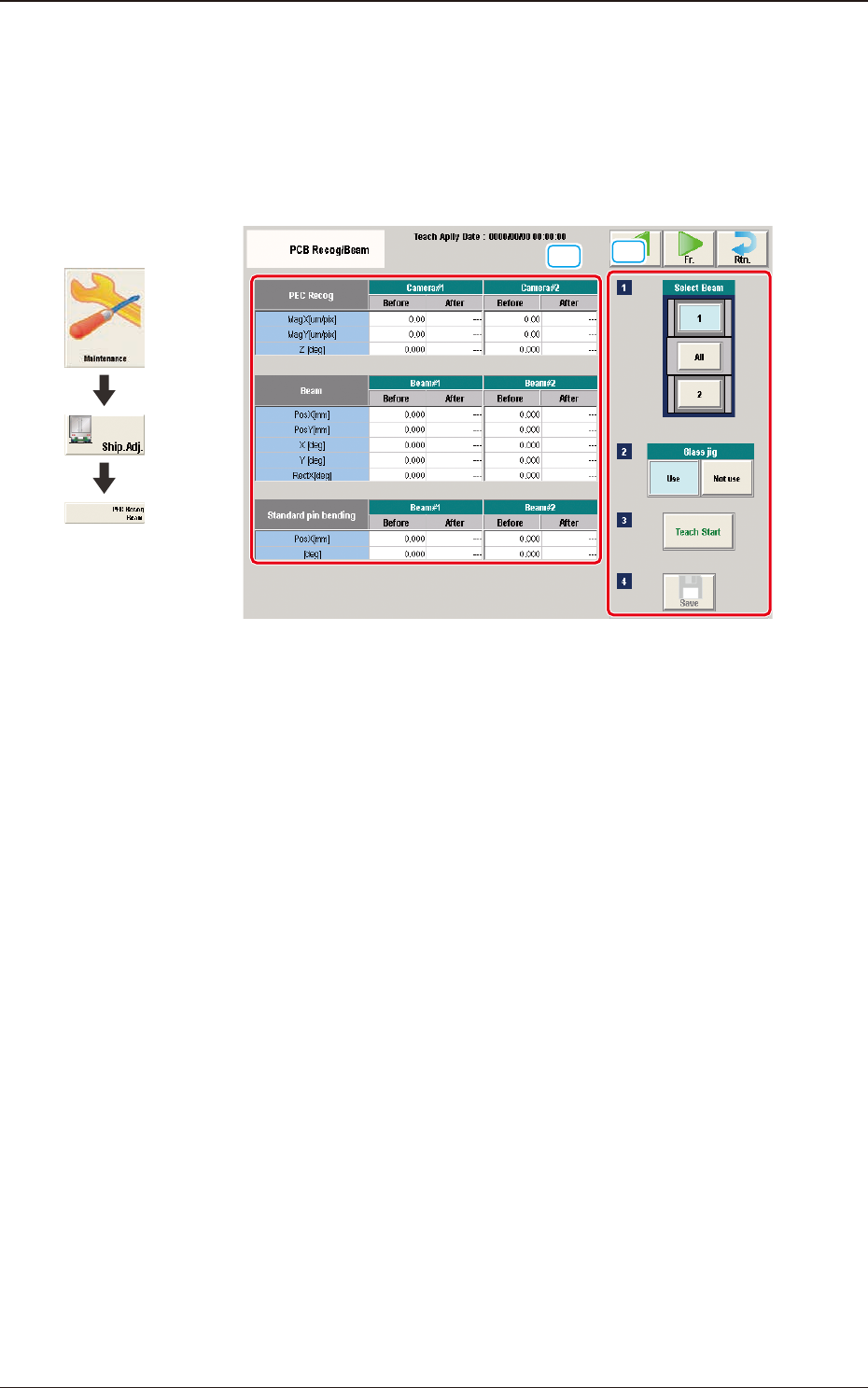
5.8 "PCB Recog/Beam" Window
The corresponding window enables you to perform the teaching operation for the
PEC recognition camera offset (Magnication X(Horizontal), Y(Vertical) and
Z(Angle), Beam offset (Beam X(Horizontal), Beam Y(Vertical), Beam Angle X
and Y).
[1]
[2]
F3A35
[1] Teaching Data Display Section
Displayed are the offset data items for the designated beam.
[2] Teaching Procedure Display Area
Displayed are the buttons to be used for the teaching operations.
Select Beam
Each PEC recognition camera/beam in the graphic image of the machine is
provided with a button function. Select the PEC recognition camera/beam for
which the teaching operation is performed.
Glass Jig
[Use] button
When this button is pressed to use the glass component jig, the color of
the button turns light blue.
[Not use] button
When this button is pressed not to use the glass component jig, the color
of the button turns light blue.
[Teach Start] button
When pressed, this button executes the teaching operation.
Graphic
Development
5.8 "PCB Recog/Beam" Window

3OM-1751
1-481303-001
[Save] button
When this button is pressed, the teaching results are saved.
•
Glass Jig PCB JG-0166 (PEC Recognition Calibration Jig)
For the "PEC Recognition Camera & Beam Offset" teaching, the following
glass jig PCB is used.
Before the teaching operation, position and clamp the glass jig PCB on the PCB
positioning center.
·
Teaching Procedure
Procedure
(1) Select the Beam (1 or 2) for which the teaching is performed.
(2) Press the [Use] button in the "Glass Jig" section.
(3) Press the [Teach Start] button.
The designated beam (1 or 2) will move to the specied recognition mark
position and the following teaching operation will be performed.
•
PEC Recognition Camera Magnication X (Horizontal), Y (Vertical),
Z (Angle) Teaching (Camera 1 or 2)
•
Beam X (Horizontal) and Y (Vertical) Offset Teaching (Beam 1 or 2)
•
Beam Angle Z, Angle Y, Rectangular X Offset Teaching (Beam 1 or 2)
•
Pilot Pin Bending Position X Side, Angle (Beams 1 and 2)
•
When the teaching is performed, the start conditions are checked
and the head except for designated, is evacuated automatically.
•
When any recognition error occurs during the teaching operation or
the [STOP] button is pressed on the operation penal, the machine
is stopped temporarily. In this case, re-start is available.
•
During this temporary stop mode, the selection of any other menu
item is unavailable.
When the teaching is completed, the designated head returns to
the home position automatically.
The teaching results and mark recognition results during the
teaching (XY Angles) are displayed in the display area in the "PEC
Recognition Camera & Beam Offset" window.
5.8 "PCB Recog/Beam" Window
3OM-1751
1-491303-001
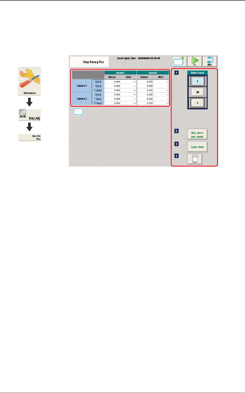
5.9 "Cmp Recog Pos" Window
This window enables you to perform a teaching operation on the component
recognition camera offsets (X (mm) Horizontal, Y (mm) Vertical, and Z (deg)
Theta).
[1]
[2]
F3A36
[1] Teaching Data Display Section
Displayed are the each offset data items for the designated camera and head.
[2] Teaching Procedure Display Area
Displayed are the buttons to be used for the teaching operations.
Select head
In this section, the buttons showing the component recognition cameras
corresponding to each head are displayed as images.
Select the component recognition camera for which the teaching is
performed.
[Noz. Place. Pos. move] Button
Using this button, the head is moved to the position where the nozzle to be
used for the teaching can be attached easily.
[Teach Start] button
When pressed, this button executes the teaching operation.
[Save] button
When this button is pressed, the teaching results are saved.
Graphic
Development
5.9 "Cmp Recog Pos" Window