3OM-1751-002w_G5S.pdf - 第182页
3OM-1751 2-14 1303-001 2.1.9 "Support pin pos" T ab Sheet [1] F3B14 [1] L, R X [mm], Y [mm], Z [deg], L [mm] These offset parameters are to be corrected when the support pin data is converted. These offset para…
3OM-1751
2-13
1303-001
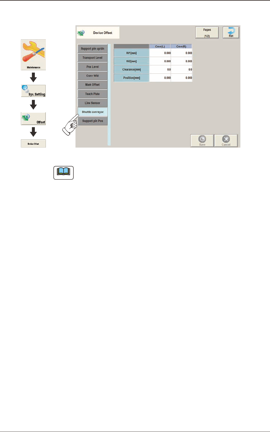
2.1.8 "Shuttle conveyor" Tab Sheet
F3B13
Note
This setting is used as an option.
Graphic
Development
2.1 "Device Offset" Window
3OM-1751
2-141303-001
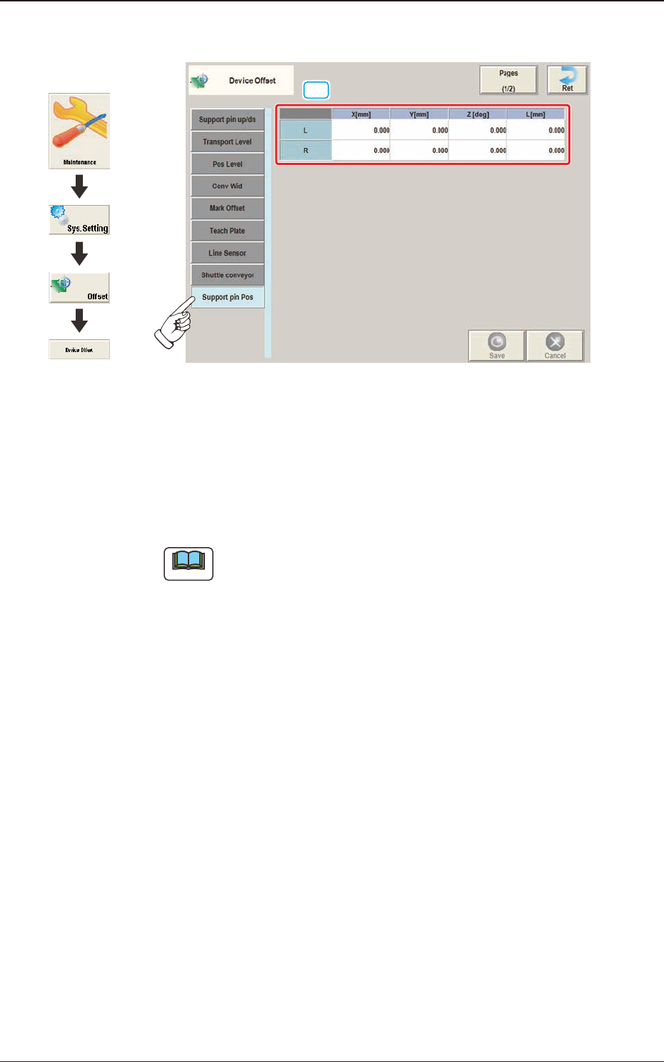
2.1.9 "Support pin pos" Tab Sheet
[1]
F3B14
[1] L, R
X [mm], Y [mm], Z [deg], L [mm]
These offset parameters are to be corrected when the support pin data is
converted. These offset parameters are calculated automatically in the
support pin teaching operation.
Note
When this teaching is performed, the dedicated teaching pins are required.
Graphic
Development
2.1 "Device Offset" Window
3OM-1751
2-15
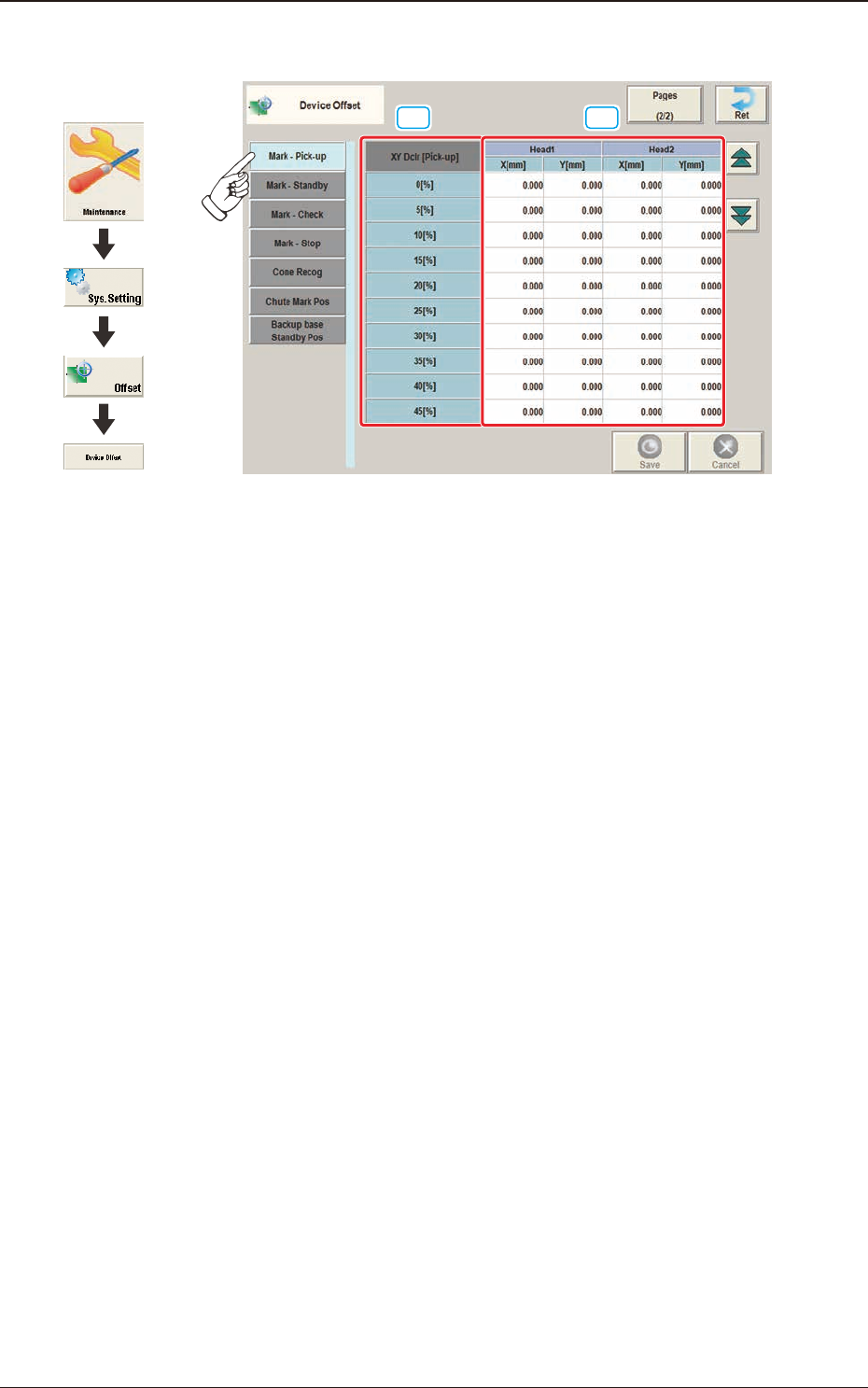
2.1.10 "Mark-Pick-up" Tab Sheet
[1] [2]
F3B15
[1] XY Dclr [Pick-up]
0 [%] to 45 [%]
The XY speed reduction rate is displayed in these data boxes.
[2] Head 1, 2
X [mm], Y [mm]
The deviation for the head X, Y when the head is moved from the reference
mark to the pick-up position, is corrected based on the XY speed reduction
rate.
1303-001
2.1 "Device Offset" Window
Graphic
Development