3OM-1751-002w_G5S.pdf - 第85页
3OM-1751 1-31 Notice • The teaching operation might af fect the component placement accuracy . Therefore, consult with out marketing department or sales agent. • Some operations require special jigs (options). Consult ou…

3OM-1751
1-301303-001
Button Name Teaching Outline
NL-Axis Org Master Noz Lv
When this button is pressed, the teaching operations for avoiding the impact
given to the component in the NL-axis rotation, and for the master nozzle
lower surface level reference position, are performed.
Pick-up Lv Stk Lv Set
When this button is pressed, the automatic entry of numerical values into
the offset data box is enabled by means of entering the data obtained in the
measurement with the jig placed, in this data box.
Chute Lv
When this button is pressed, the head up/down offset is calculated
automatically by means of teaching the chute level when the head is
changed.
Cmp Recog Light
The corresponding window enables the operator to perform the teaching
operation for the lighting for the component recognition camera.
PCB Recog Light
The corresponding window enables the operator to perform the teaching
operation for the lighting for the PCB recognition camera.
Mark Light
The corresponding window enables the operator to perform the teaching
operation for the Mark Light.
Cmp Recog Mag
The corresponding window enables the operator to perform the teaching
operation on the magnication of the PEC recognition camera.
PEC Recog_Beam
When this button is pressed, the teaching operation for the PEC recognition
camera offsets (Magnications X (Horizontal), Y (Vertical) and Z (Angle)
and the beam offsets (Beam X (Horizontal), Beam Y (Vertical), Beam
Angle X and Beam Angle Y) are performed.
Cmp Recog Camr Pos
When this button is pressed, the teaching operations for the component
recognition camera position (X (Horizontal), Y (Vertical) and Z (Angle)
are performed.
Hd Rot Axis Offset
When this button is pressed, the teaching for the designed distance from
the locating position reference to the camera center based on the placement
position reference, is performed.
Hd Rot Center
When this button is pressed, the teaching is performed to correct the
deviation of the head rotation center from the PEC recognition camera
center reference value using the jig component.
Fly Recog Camr
(Base Mark Position)
When this button is pressed, the image capture timing is taught after nding
the deviation of component recognition camera position in stopped image
shooting, from the position in fry recognition image capturing.
Noz Stk Pos
When this button is pressed, the teaching is performed for keeping the
nozzle stocker position (machine coordinate reference).
Noz Incln
When this button is pressed, the teaching for the offset data to collect the
head/nozzle inclination is performed.
Noz Lv/Pos.
When this button is pressed, the teaching operations are performed for the
nozzle lower surface level for the normally attached nozzle and for the
deviation of the head rotation center to the nozzle end position to the head
from the reference values.
Support pin Pos
The corresponding window enables the operator to perform the teaching
operation for the PCB support pin position (X-axis, Y-axis).
T3A4
5. "Shipment Adj." Window

3OM-1751
1-31
Notice
•
The teaching operation might affect the component placement
accuracy. Therefore, consult with out marketing department or sales
agent.
•
Some operations require special jigs (options).
Consult our marketing department or sales agency before
performing any teaching operations.
•
Follow the teaching procedures in the specied order. Otherwise,
some trouble (such as inaccurate component placement, frequent
mechanical errors, etc.) will arise.
•
Before performing any teaching operation, conrm that the
component recognition offset jig, the jig setting position, and the
back light stage (teaching plate) are not nicked and stained.
1303-001
5. "Shipment Adj." Window
3OM-1751
1-321303-001
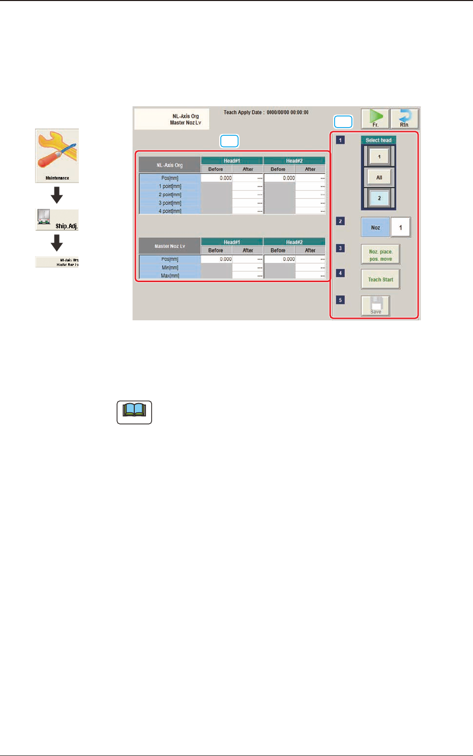
5.1 "NL-Axis Org Master Noz Lv" Window
This window enables the operator to perform the teaching on the offsets to correct
the difference in level between the nozzle up/down mechanism and the nozzle
roller to avoid the impact given to the component in the NL-axis rotation.
[2]
[1]
F3A24
[1] Teaching Data Display Section
Displayed are each offset data for the designated head.
Note
When the multi-functional head has been selected, they are not displayed.
NL-Axis Org
The nozzle level is measured using the line sensor and based on the data
read after the NL-axis is moved to four positions, the NL-axis origin offset is
calculated automatically.
Before
: Shows the value before the teaching
After
: Shows the resultant value after the teaching
Master Noz Lv
Displayed is the offset data (L Up/Down (mm)) for the designated nozzle.
Before
: Shows the value before the teaching
After
: Shows the resultant value after the teaching
Graphic
Development
5.1 "NL-Axis Org Master Noz Lv" Window