xp141-241-341-5.0E.pdf - 第101页
FK-9F98- 29 XP Series Training Text for Service Engineers Edition 5.0 XP241 – Chapter 2 Zero Setting Page 1 of 4 Fuji Machine Mfg. Co., Ltd. Okazaki. SMT Equipment Quality Assurance Dept . 2 – 1 CS Section Chapter 2 – Ze…

C
C
h
h
a
a
p
p
t
t
e
e
r
r
2
2
Z
Z
e
e
r
r
o
o
S
S
e
e
t
t
t
t
i
i
n
n
g
g
s
s
FK-9F98-29 XP Series Training Text for Service Engineers
Edition 5.0 XP241 – Chapter 2 Zero Setting Page 1 of 4
Fuji Machine Mfg. Co., Ltd. Okazaki.
SMT Equipment Quality Assurance Dept.
2 – 1 CS Section
Chapter 2 – Zero setting
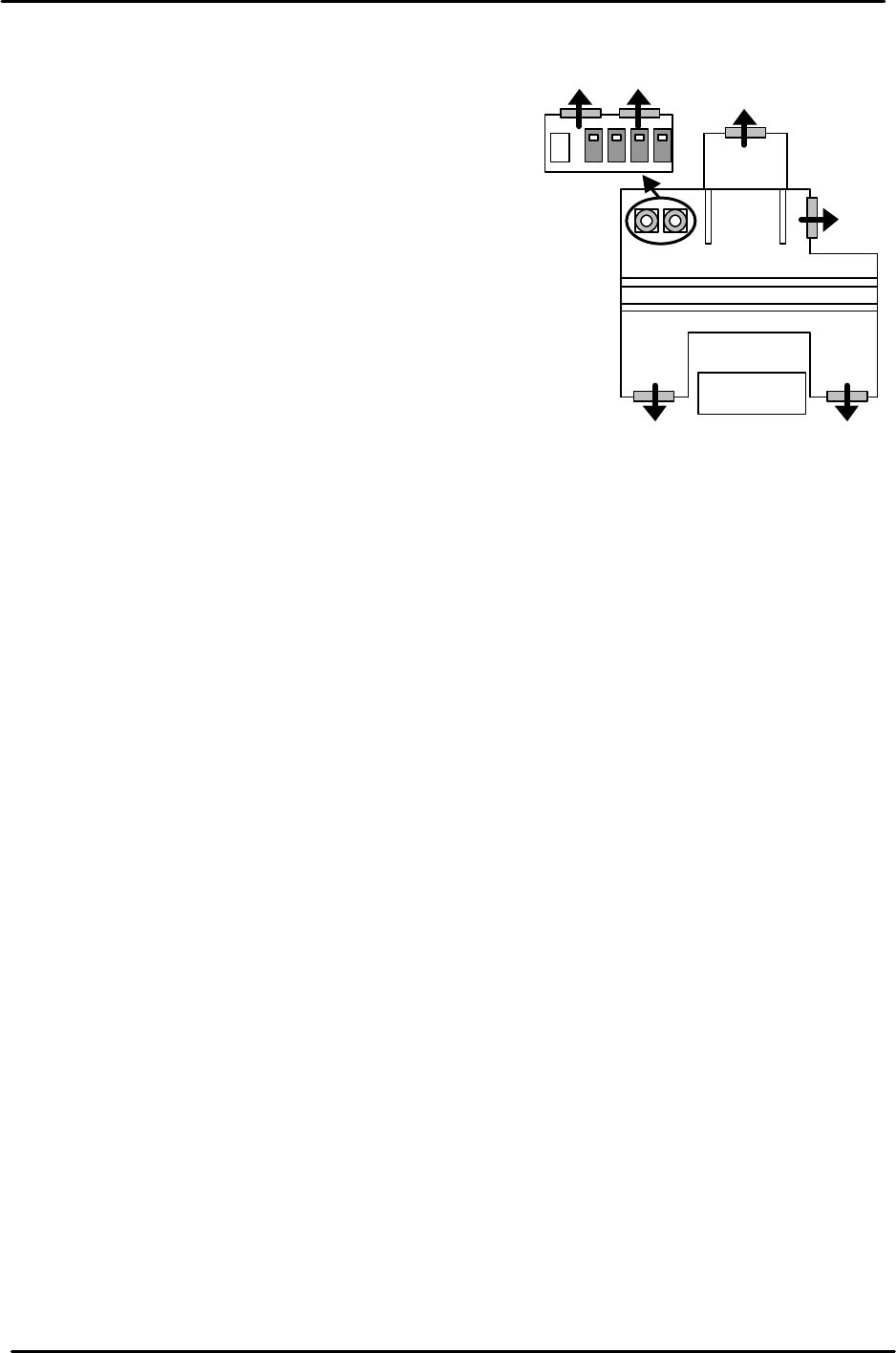
2.1 Cooling Fan Check
1. When the machine has been turned ON and the OS
has booted up check that the cooling fans are
operating properly and rotating in the correct
direction.
2. There is a servo amplifier rack in the electric box at
the right hand corner of the machine rear. On top,
there are two cooling fans. Check that they are
operating properly and rotating in the correct
direction, so that the air flows outwards.
2.2 Checking the Standard Proper
1. Check that the fixed values entered in the machine proper data match those in the
standard proper list.
Note: set the proper data item “TRAY DETECTION MOTION” to “0” until the MTU is
adjusted in chapter 5. After the MTU has been adjusted, set the proper data to “1”.
2.3 Checking the Digital Amplifier Parameters
• Equipment: Digital Operator (JUSP-0P02A)
1. Press the M/C emergency stop so that the 200V power supply to the servos is cut.
2. Connect the digital operator to the relevant servo amplifier, (“bb” displays at the screen).
3. Press [DSPL/SET] to select the channel mode (Pn000).
4. Specify the number of the channel to be checked, then press [DATA/ENTER] to display.
5. Ensure that the values match those listed in the machine servo amp parameter table.
6. When you have completed checking the parameters, return to the”bb” screen.
7. When the setting is completed, Re-boot the machine.
Example: [-bb] – [DSPL/SET] – [Pn-00] – [DATA/ENTER] – [Pn.001](setting)
-
¬
M/C front
MTU
FK-9F98-29 XP Series Training Text for Service Engineers
Edition 5.0 XP241 – Chapter 2 Zero Setting Page 2 of 4
Fuji Machine Mfg. Co., Ltd. Okazaki.
SMT Equipment Quality Assurance Dept.
2 – 2 CS Section
2.4 Setting the Servo Amplifier Defaults
1. Set each of the axes to their mechanical stoppers on the minus side. (Please refer to the
mechanical stopper location diagrams in the back of this manual.)
Note: there is NO Minus (-) mechanical stopper on the Q-axis, so set the reference
position where the spline shaft bearing retainer bolt faces out towards the front of the
machine.
Note: cut the servo (200V) when setting each of the
axes to the Minus (-) mechanical stopper.
Note: be careful when using the [JOG] key to set the
T-axis to the Minus (-) mechanical stopper position.
To prevent the T-axis from crashing avoid jogging the
T-axis when in close proximity to the Minus (-)
mechanical stopper.
2. Press the emergency stop button so that the 200v
power supply cuts out.
3. Connect the digital operator to the target servo amp.
(“bb” is displayed on the screen).
4. Press [DSPL/SET] to select the channel mode
(Fn000).
5. Select channel (Fn008) by pressing the [UP] key.
6. Press [DATA/ENTER] to display “PGCL1”.
7. Press [UP] to set it to “PGCL5”.
8. Press [DSPL/SET] and “done” displays.
9. Press [DATA/ENTER] to return to the support mode (Fn008).
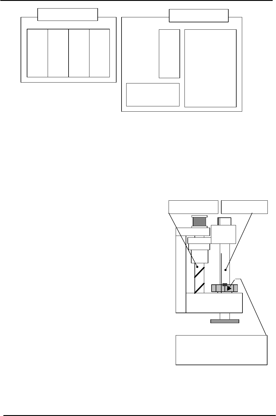
Servo box (rear)
T-axis servo amp
U-axis servo amp
Q-axis servo amp
Z-axis servo amp
Y-axis servo amp.
X-axis servo amp.
Strobe Power
supply
Servo box (front)
Spline shaftZ-axis ball screw
The reference position is where
the spline shaft bearing retainer
bolt faces the M/C front.