xp141-241-341-5.0E.pdf - 第43页
FK-9F98- 29 XP Series Training Text for Service Engineers Edition 5.0 XP141 – Chapter 5 Peripheral Adjustments Page 5 of 16 Fuji Machine Mfg. Co., Ltd. Okazaki SMT Equipment Quality Assurance Dept. 5 – 5 CS Section Confi…
FK-9F98-29 XP Series Training Text for Service Engineers
Edition 5.0 XP141 – Chapter 5 Peripheral Adjustments Page 4 of 16
Fuji Machine Mfg. Co., Ltd. Okazaki
SMT Equipment Quality Assurance Dept.
5 – 4 CS Section
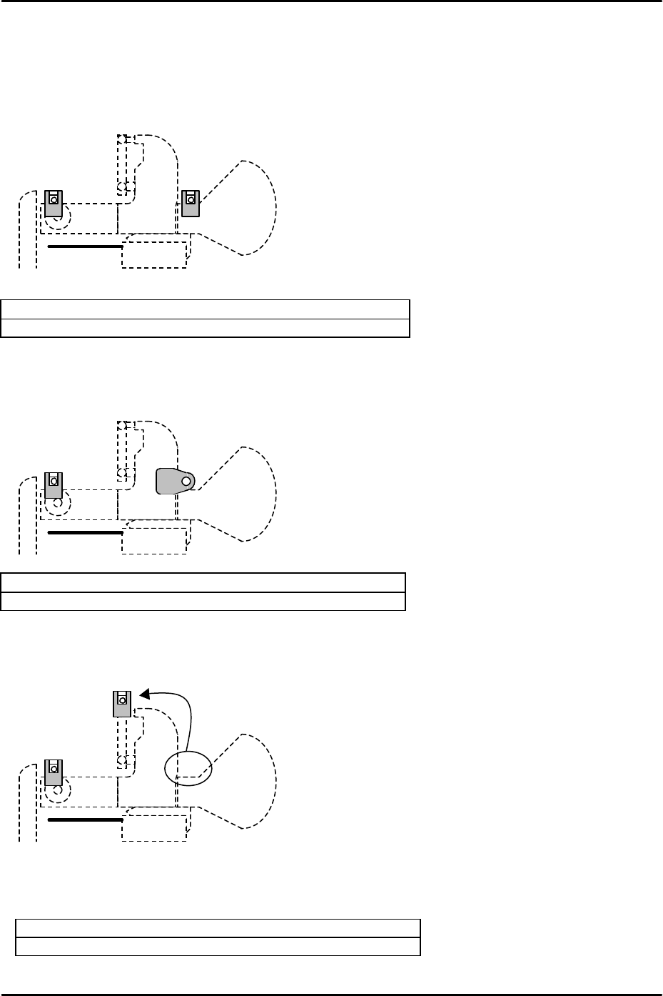
Currently there are 5 different types of tape leaf/feeder check sensor configuration on XP1.
The type of configuration depends on the specification of the machine and the date of
shipment. The 5 different configurations are as follows:
Configuration A (Xno.93 or earlier)
Feeder tape leaf detection sensor: Yamatake LED type
Feeder set check sensor: Yamatake LED type
Configuration B (EC type Xno.94 or later)
Feeder tape leaf detection sensor: Yamatake LED type
Feeder set check sensor: Schmersl LED type
Configuration C (AA mode machines)
To enable MFU detachment during production the feeder set check sensor has been moved
and the beam functions as an interlock in the feeder indexing lever area.
Feeder tape leaf detection sensor: Yamatake LED type
Feeder set check sensor: Yamatake LED type
FK-9F98-29 XP Series Training Text for Service Engineers
Edition 5.0 XP141 – Chapter 5 Peripheral Adjustments Page 5 of 16
Fuji Machine Mfg. Co., Ltd. Okazaki
SMT Equipment Quality Assurance Dept.
5 – 5 CS Section
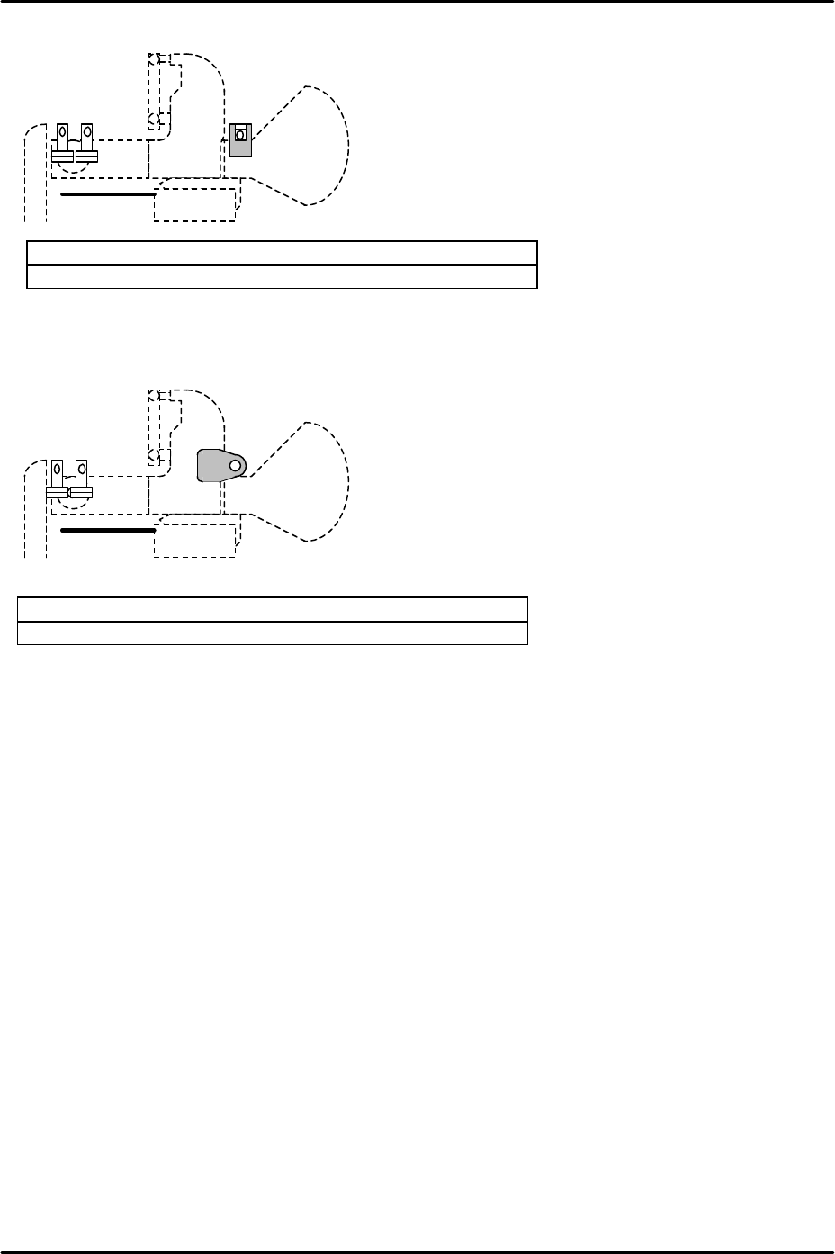
Configuration DA (Double detection sensor Xno.93 or earlier)
Feeder tape leaf detection sensor: Yamatake fiber type
Feeder set check sensor: Yamatake LED type
Configuration DB (Double detection sensor Xno.94 or later)
Feeder tape leaf detection sensor: Yamatake fiber type
Feeder set check sensor: Schmersl LED type
FK-9F98-29 XP Series Training Text for Service Engineers
Edition 5.0 XP141 – Chapter 5 Peripheral Adjustments Page 6 of 16
Fuji Machine Mfg. Co., Ltd. Okazaki
SMT Equipment Quality Assurance Dept.
5 – 6 CS Section
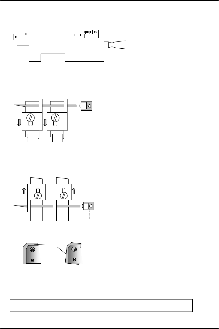
Adjustment for configuration A
1. Clamp the MFU and load two feeder sensor adjustment jigs (Z9631ADEPJ1000) at slots
D47 and D49 at side 1.
2. Fix the front sliding attachments at their backward limit (in the direction away from the
machine interior) and insert a 1.8mm diameter wire jig between the holes in the
attachments. Adjust the tape leaf check sensor position so that the point where the
sensor beam is emitted is aligned with the center of the wire jig.
3. Fix the rear sliding attachments at their forward limit (in the direction towards the machine
interior) and insert a 1.8mm diameter wire jig between the holes in the attachments.
Adjust the feeder set check sensor position so that the point where the sensor beam is
emitted is aligned with the center of the wire jig.
4. Check the tilt of both sensors.
5. Move the feeder sensor jigs to D2 and D4 and repeat steps 2 to 4 for the sensors at the
left side of the MFU.
6. Finally check the operation of both sets of sensors by I/O.
Feeder set check sensor FH1000_1: [X017] Side 1 XY Axis Inter
Feeder tape leaf detection sensor FH1000_2: [X02C] Side1 FdeDetect
Z9631ADEPJ1000
D49D47
Tape leaf check sensor
D47
D49
Feeder set check sensor
Sensor
BKT
BKT