xp141-241-341-5.0E.pdf - 第176页
FK-9F98- 29 XP Series Training Text for Service Engineers Edition 5.0 XP241 – Chapter 8 Options Page 4 of 10 Fuji Machine Mfg. Co., Ltd. Okazaki SMT Equipment Quality Assurance Dept. 8 – 4 CS Section 8.2 Coplanarity Chec…
FK-9F98-29 XP Series Training Text for Service Engineers
Edition 5.0 XP241 – Chapter 8 Options Page 3 of 10
Fuji Machine Mfg. Co., Ltd. Okazaki
SMT Equipment Quality Assurance Dept.
8 – 3 CS Section
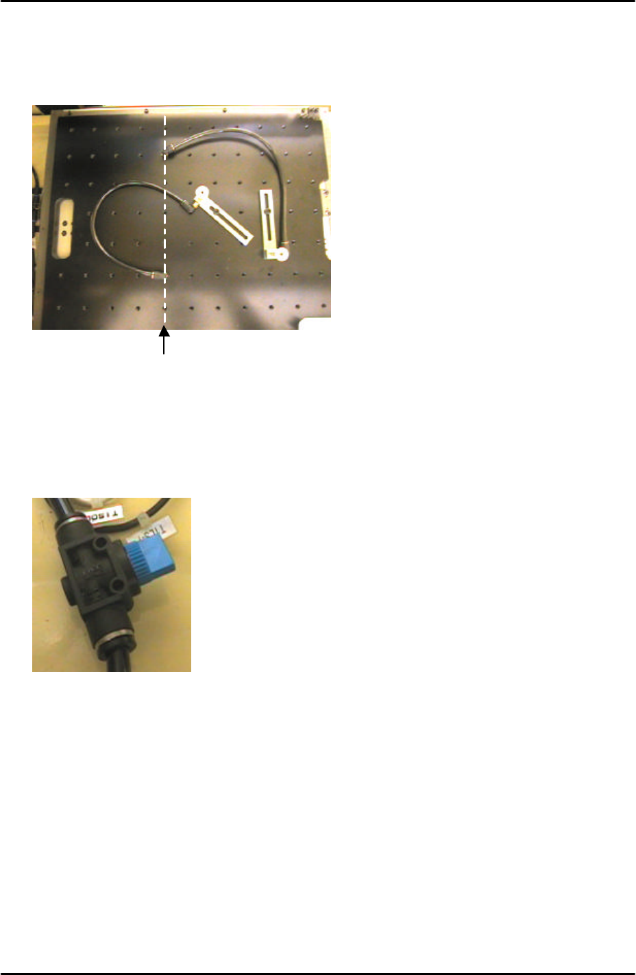
3. When setting up the vacuum back up pins on the back up plate the air terminals should
be screwed into the correct holes. The vacuum air supply is only available from the Y-
direction line 5 holes from the back up plate left hand side.
4. An air valve can be used to switch the vacuum backup air supply ON and OFF.
Only holes in this
line have a vacuum
backup air supply
FK-9F98-29 XP Series Training Text for Service Engineers
Edition 5.0 XP241 – Chapter 8 Options Page 4 of 10
Fuji Machine Mfg. Co., Ltd. Okazaki
SMT Equipment Quality Assurance Dept.
8 – 4 CS Section
8.2 Coplanarity Check Camera Adjustment
1. Equipment: Coplanarity Camera Nozzle Jig (Z9631DEPJ3410).
Coplanarity camera settings
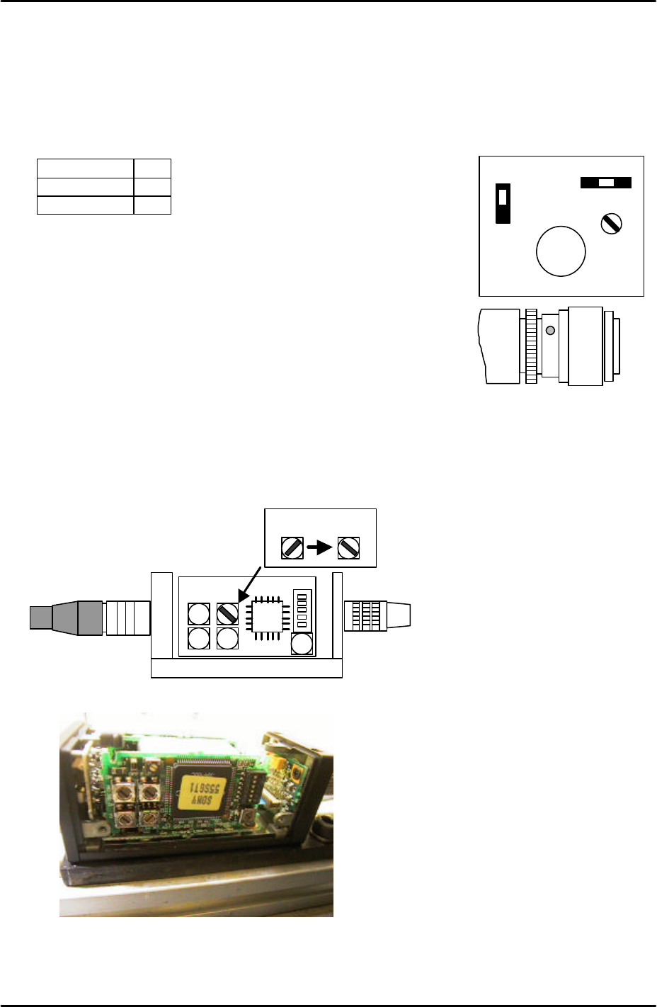
1. Set the coplanarity check camera settings and aperture as follows:
Signal 1N
Gain F
Aperture 8
Note: ensure that the lens unit is fastened to the camera unit with
adhesive (Loctite 425).
Note: Confirm that the camera lens is a 35mm lens.
2. Make sure the machine power and main breaker are OFF and
then remove the cover from the coplanarity check camera amplifier. This is located on
the machine base below the camera.
3. Set the top right rotary switch to the correct position as illustrated in the following diagram
and picture:
35mm lens
A F M
GAIN
SIGNAL
1 N
1 I
VIDEO OUT/DC IN/SYNC
35 mm
Coplanarity Camera Amplifier
Coplanarity Camera Amplifier
FK-9F98-29 XP Series Training Text for Service Engineers
Edition 5.0 XP241 – Chapter 8 Options Page 5 of 10
Fuji Machine Mfg. Co., Ltd. Okazaki
SMT Equipment Quality Assurance Dept.
8 – 5 CS Section
Vision Board Setting
1. Before proceeding with this setting make sure that the machine power and breaker are
OFF.
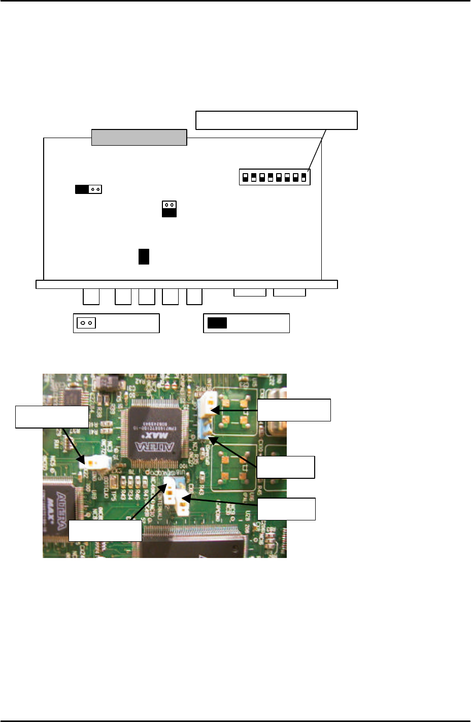
2. In order to set the vision board jumpers for use with the coplanarity check camera please
refer to the following illustration and picture:
3. It is necessary to remove the Vision board from the rack in order to set the jumpers. The
CPU board and vision boards are joined, so they must be removed together.
4. Ensure that JP2 is set to short and that JP3 is set to OPEN.
S1
.1
S1
.2
S1
.3
S1
;4
S1
.5
S1
.6
S1
.7
S1
.8
ONJP7 JP6
JP3
JP2
JP5
The dipswitch position is shown in black
Open Short
For details of the location of
the vision board please refer
to the VME rack
configuration diagram in the
supplementary information
section of this manual
JP6 is open
JP7 is shorted
JP3 is open
JP2 is shorted
JP5 is shorted
Note that the
orientation of this
picture is different to
that of the diagram
above