xp141-241-341-5.0E.pdf - 第109页
FK-9F98- 29 XP Series Training Test for Service Engineers Edition 5.0 XP241 – Chapter 3 Static Accuracy Measurement Page 4 of 6 Fuji Machine Mfg. Co., Ltd. Okazaki SMT Equipment Quality Assurance Dept . 3 – 4 CS Section …
FK-9F98-29 XP Series Training Test for Service Engineers
Edition 5.0 XP241 – Chapter 3 Static Accuracy Measurement Page 3 of 6
Fuji Machine Mfg. Co., Ltd. Okazaki
SMT Equipment Quality Assurance Dept.
3 – 3 CS Section
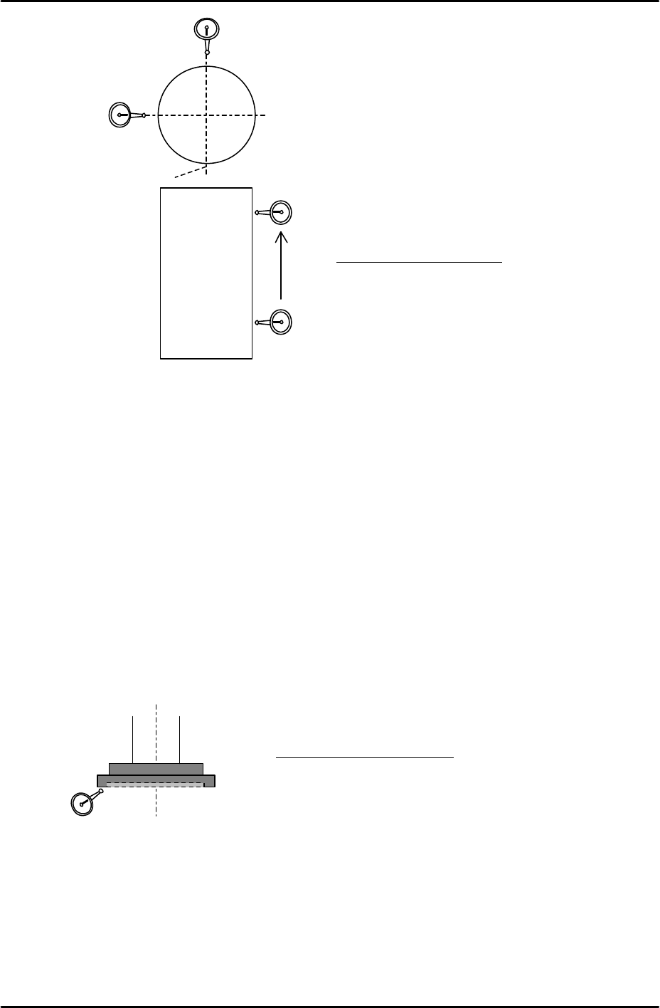
4. The difference in straightness between these two points should be within 0.03mm.
5. Repeat for the right hand side of the cylindrical jig.
3.4 Checking the Z-axis nozzle disc surface
• Equipment: Lever type dial gauge (0.002mm).
Face oscillation measurement
1. Position the Z axis 2 mm above the Z-axis minus stopper.
2. Put a dial indicator against the underside of the nozzle disc and measure the surface
oscillation by turning the Q-axis through 360 degrees.
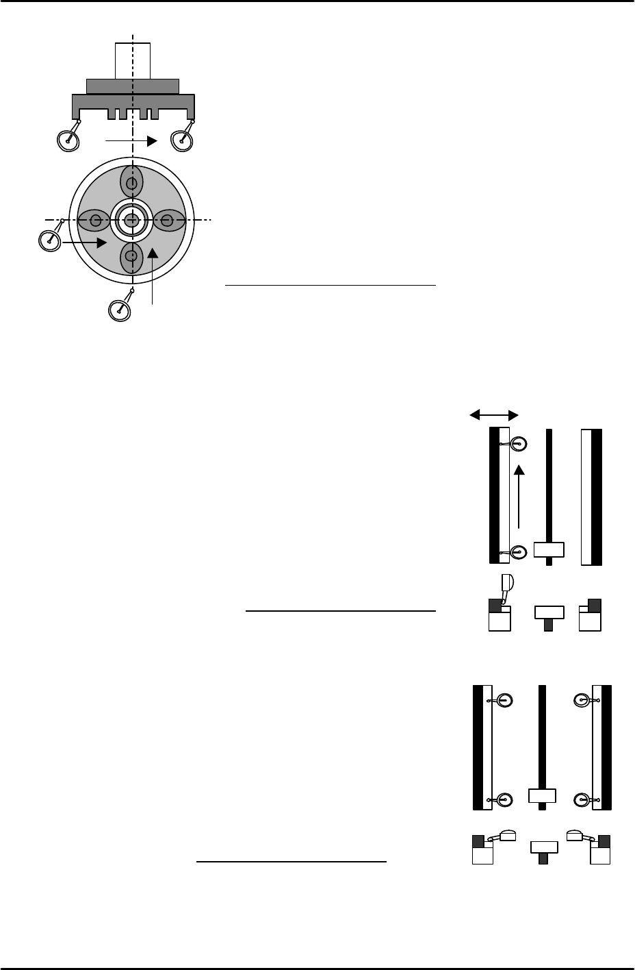
Nozzle pick-up surface parallelism measurement
1. Position the nozzle pick-up surface 2 mm above the Z-axis minus stopper.
2. Set a dial gauge on the underside of the nozzle disc, and measure the difference in
flatness from one side of the disc underside to the other. Measure in both the X and the
Y-direction.
Tolerance 0.030 / 30mm
Tolerance: 0.02mm / 360°
X-direction
Y-direction
A
0
Z9531DEPJ0060
30mm
C
FK-9F98-29 XP Series Training Test for Service Engineers
Edition 5.0 XP241 – Chapter 3 Static Accuracy Measurement Page 4 of 6
Fuji Machine Mfg. Co., Ltd. Okazaki
SMT Equipment Quality Assurance Dept.
3 – 4 CS Section
3.5 Measuring the parallelism of the U-axis
tray and fixed rail
• Equipment: Lever type dial gauge (0.01 mm).
1. Attach the dial gauge to the placing head (an extension
bar is necessary).
2. Moving the dial gauge along the Y-axis, measure the side
of the fixed rail as illustrated in the diagram.
3.6 Measuring the flatness of the U-axis tray
• Equipment: Lever type dial gauge (0.01mm).
1. Attach the dial gauge to the placing head (an extension
bar is necessary).
2. Measure the flatness (of the plastic bar) at the tray parts
pick-up position.
Tolerance: +/- 0.020mm / 50mm
0
+ -
500
250
Tolerance: 0.10mm / 500mm
C
D
0
A
B
Tolerance: 0.10mm / 500mm
FK-9F98-29 XP Series Training Test for Service Engineers
Edition 5.0 XP241 – Chapter 3 Static Accuracy Measurement Page 5 of 6
Fuji Machine Mfg. Co., Ltd. Okazaki
SMT Equipment Quality Assurance Dept.
3 – 5 CS Section
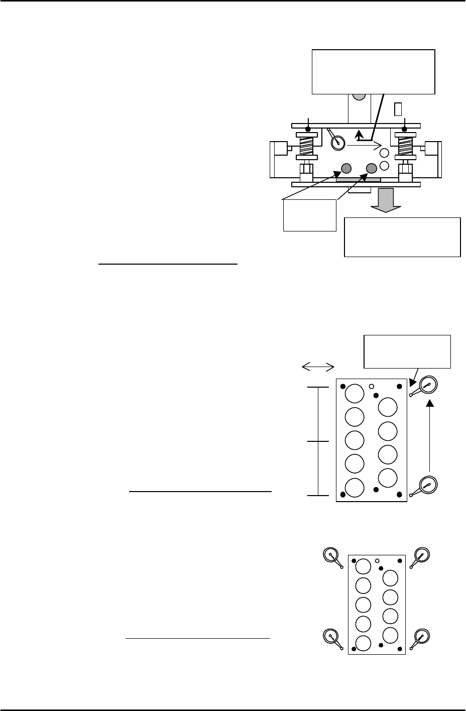
3.7 Measuring the parallelism of the U-axis shuttle
• Equipment: Lever type dial gauge (0.01mm).
1. Extend the U-axis shuttle manually until it
reaches the minus (-) mechanical stopper.
2. Attach the dial gauge to the placing head (an
extension bar is necessary).
3. Measure the parallelism at the edge of the
shuttle clamper discs. (Measure from [0] position
to [A] position).
4. If it is out of the tolerance, adjust the bolt on the
LM slider. After the bolt is tightened remeasure
the parallelism as it may have changed.
3.8 Measuring the parallelism and flatness of the nozzle station
• Equipment: Lever type dial gauge (0.01mm).
Nozzle station parallelism measurement
1. Attach the dial gauge to the placing head (an
extension bar necessary).
2. Measure the parallelism from the reference
position in the X- and Y-direction.
Note: if the value is out of the tolerance, please
contact FUJI.
Nozzle station flatness measurement
1. Attach the dial gauge to the placing head (an extension bar is necessary).
2. Measure the height of the four corners of the nozzle station, ensuring any deviation is
within 0.06 mm.
Note: If the value is out of the tolerance, please contact FUJI.
[0]
A
Adjust
these bolts.
Measure the parallelism
at the edge of the shuttle
claws by the dial gauge.
Extend the shuttle to the
M/C front side. (to the
minus mechanical stopper)
Tolerance: 0.20mm / 100mm
+ -
0
280
140
0
Measure the side of
the nozzle station
Tolerance: 0.06mm / 280mm
B
C
D
0
A
Tolerance: Deviation 0.06mm