xp141-241-341-5.0E.pdf - 第28页
FK-9F98- 29 XP Series Training Text for Service Engineers Edition 5.0 XP141 – Chapter 4 Loader Adjustment Page 3 of 12 Fuji Machine Mfg. Co., Ltd. Okazaki. SMT Equipment Quality Assurance Dept. 4 – 3 CS Section 4.3 Adjus…
FK-9F98-29 XP Series Training Text for Service Engineers
Edition 5.0 XP141 – Chapter 4 Loader Adjustment Page 2 of 12
Fuji Machine Mfg. Co., Ltd. Okazaki.
SMT Equipment Quality Assurance Dept.
4 – 2 CS Section
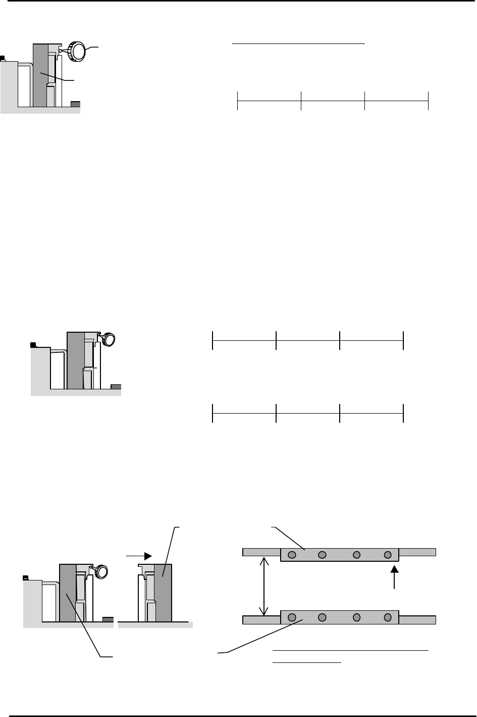
Fixed Rail Flatness Measurement
Note: Do not use the conveyor auto width changer, as this is not adjusted yet.
1. Adjust the conveyor width to 200mm.
2. Set the dial gauge on the underside of the board clamper at the fixed rail side. Measure the
flatness and record the measurements on the adjustment check sheet.
3. Measure the flatness of the underside of the board clamper at the adjustable rail side.
4. Set the dial gage on the fixed rail to “0”, and measure the difference between the fixed rail
and the adjustable rail. Add the difference to the flatness value of the adjustable rail side
measured in step 3. If the values are out of tolerance please contact FUJI.
Dial Gauge
Reference side of the
Conveyor
Viewed from the right side
of the machine
0450 300 150
( ) ( ) ( ) 0
(mm)
(mm)
Tolerance: ±0.05 / 450 mm
Reference side of the
conveyor
Viewed from the right
side of the machine
(mm)
0
450 300 150
( ) ( ) ( )
0
0450 300 150
( ) ( ) ( ) ( )
(mm)
(mm)
(mm)
Reference Conveyor
Viewed from the right
side of the machine
Movable conveyor
200mm
Tolerance: whole deviation to be
within 0.20mm
FK-9F98-29 XP Series Training Text for Service Engineers
Edition 5.0 XP141 – Chapter 4 Loader Adjustment Page 3 of 12
Fuji Machine Mfg. Co., Ltd. Okazaki.
SMT Equipment Quality Assurance Dept.
4 – 3 CS Section
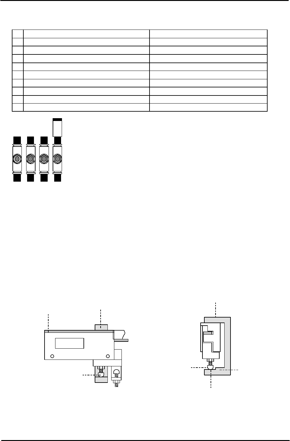
4.3 Adjusting the Conveyor Speed Controllers
Speed Controller Number of times from fully closed
1 In-conveyor board lifter (UP) Approximately ¼ turn.
2 In-conveyor board lifter (DOWN) Approximately 1 turn.
3
Main conveyor board clamp (SLOW) ½ turn.
4
Main conveyor board unclamp (SLOW) 1.5 turns.
5
Main conveyor board unclamp (FAST) 4 turns.
6
Main conveyor board clamp (FAST) 4 turns.
7 Board stopper (UP) 4 turns.
8 Board stopper (DOWN) 4 turns.
9 Board vacuum (Option) 1 turn.
4.4 Board clamper adjustment
1. Equipment: U-shaped jig (Z9423DBQJ0010), Lifter Height Adjustment Plate Jig
(Z9623DBQJ1560) x2, Lifter Height Adjustment Cylindrical Jig (Z9623DBQJ1550).
2. Lower the main lifter.
3. Use the U-shaped jig to set the vertical distance between the board clamper adjustment
bolt and the conveyor rail top surface to 59.74 +/- 0.05mm. Please see the diagram
below:
4. Adjust the distance by adjusting the length of the board-clamper height adjustment bolt.
There are four bolts in total, two on the reference side of the conveyor, and two on the
adjustable side. Note that the clamper should be in contact with the underside of the
conveyor rail.
3 4 5 6
Note
: check the main conveyor board clamp/unclamp speed controllers
after the main lifter upper limit/downward limit sensor adjustment is
complete.
U-shaped
Jig
Height Adjust
Bolt
Surface B
does not go
through
Surface A
goes through
Clamper
U-shaped
Jig
Height Adjust
Bolt
Conveyor
Rail
FK-9F98-29 XP Series Training Text for Service Engineers
Edition 5.0 XP141 – Chapter 4 Loader Adjustment Page 4 of 12
Fuji Machine Mfg. Co., Ltd. Okazaki.
SMT Equipment Quality Assurance Dept.
4 – 4 CS Section
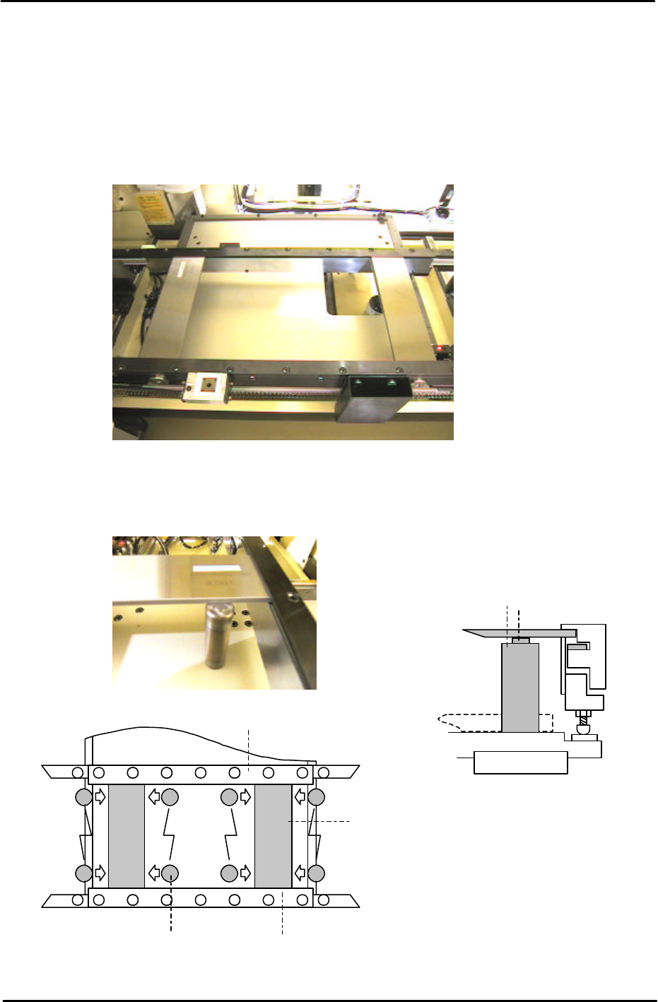
5. Raise the main lifter. Under these conditions there should be no gap between the
clamper and the conveyor rail. If there is a gap it is necessary to adjust the stroke of the
main lifter cylinder (under the main table) until the board clamper contacts the underside
of the conveyor rail. Note that normally the stroke is already set and does not need to be
adjusted.
6. Clamp the two Lifter Height Adjustment Plate Jigs in the main table as shown in the
picture below:
7. Under these conditions re-adjust the board clamper adjustment bolts until surface C of
the Cylindrical Jig can slide in under the plate jigs as illustrated in the following pictures:
Each plate jig should be clamped 50mm from the end of
the main conveyor rail
Lifter Plate
C goes
through
D does not go
through
Movable
Rail
Plate Jig
Reference
Rail
Cylindrical Jig
Note that the back up plate
must be removed