xp141-241-341-5.0E.pdf - 第23页
FK-9F98- 29 XP Series Training Text for Service Engineers Edition 5.0 XP141 – Chapter 3 Static Accuracy Measurement Page 1 of 2 Fuji Machine Mfg. Co., Ltd. Okazaki SMT Equipment Quality Assurance Dept. 3 – 1 CS Section C…

C
C
h
h
a
a
p
p
t
t
e
e
r
r
3
3
S
S
t
t
a
a
t
t
i
i
c
c
A
A
c
c
c
c
u
u
r
r
a
a
c
c
y
y
M
M
e
e
a
a
s
s
u
u
r
r
e
e
m
m
e
e
n
n
t
t
FK-9F98-29 XP Series Training Text for Service Engineers
Edition 5.0 XP141 – Chapter 3 Static Accuracy Measurement Page 1 of 2
Fuji Machine Mfg. Co., Ltd. Okazaki
SMT Equipment Quality Assurance Dept.
3 – 1 CS Section
Chapter 3 – Static Accuracy Measurement
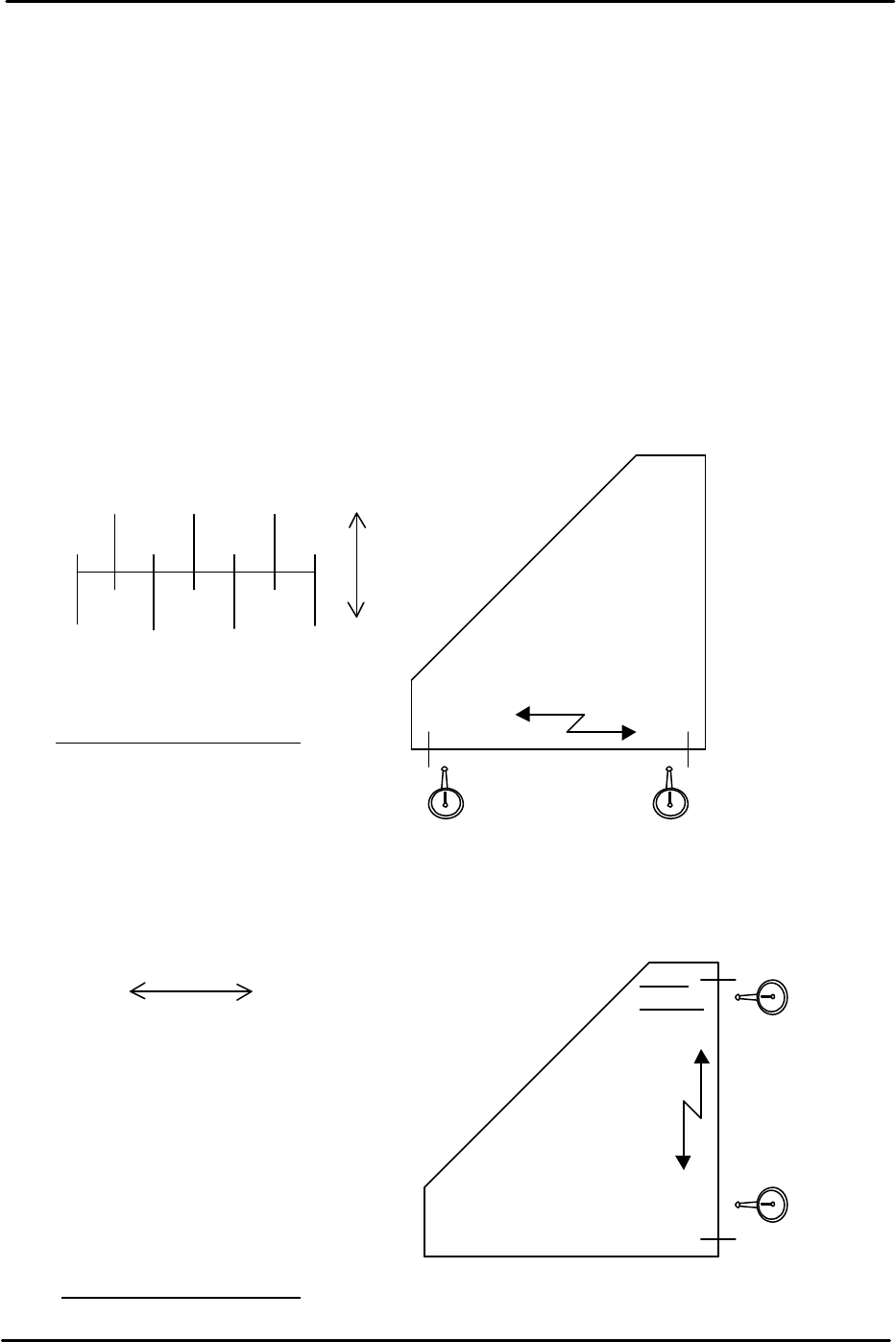
3.1 Checking the straightness of the X/Y axes
1. Equipment: perpendicular measurement jig (Z9531DEPJ0050). Lever type dial gage
(0.01mm).
2. Attach the dial gage to the placement head (an extension bar is necessary).
3. Place the perpendicular measurement jig (Z9531DEPJ0050) on to the conveyor. Adjust
the jig position so that when running the dial gage along the jig in the X direction, the
0mm and 300mm point values are both “0” (i.e. the jig is parallel to the X axis).
4. If the XY-axis squareness needs to be measured, it is better to perform measurement
(3.2) first, before measuring the Y-axis straightness.
5. Measure the Y axis straightness in the same way as the X-axis. Measure in the part
placement area of the main conveyor.
250 150 50
300 200 100 0
( ) ( ) ( )
0 ( ) ( ) ( )
+
–
Tolerance: 0.06/300 (mm)
0
0X-direction
Z9531DEPJ0050
300mm
point
0 point
Movement distance of the X-axis
0
( )
( )
( )
( )
( )
0
300
250
100
150
100
50
0
+ -
Movement distance of the Y-axis
0
0
Y-direction
Z9531DEPJ0050
Tolerance: 0.06/300 (mm)
300m
m point
0 point
FK-9F98-29 XP Series Training Text for Service Engineers
Edition 5.0 XP141 – Chapter 3 Static Accuracy Measurement Page 2 of 2
Fuji Machine Mfg. Co., Ltd. Okazaki
SMT Equipment Quality Assurance Dept.
3 – 2 CS Section
3.2 Measuring the squareness of the XY axis
1. Equipment: perpendicular measurement jig (Z9531DEPJ0050). Lever type dial gage
(0.01mm).
2. Load the perpendicular measurement jig on the conveyor, and position it so that the X-
side is parallel with the X-axis.
3. With the jig in this position, measure the Y-direction side. This indicates the Y-axis
orientation that is perpendicular to the X-axis.
4. Measure in the part placement area of the main conveyor.
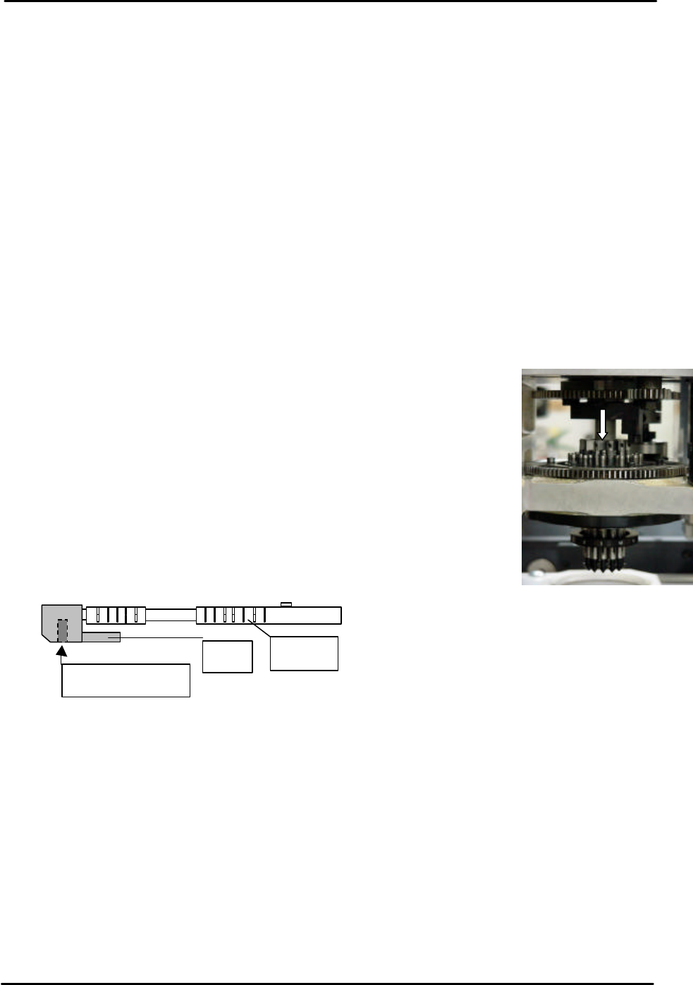
3.3 Measuring the piston deviation
1. Equipment: lever type dial gage (0.01mm).
2. Bring the number 1 nozzle to the front of the machine and set the
dial gage on the top of the nozzle piston as indicated in the adjacent
picture:
3. Using the number 1 nozzle piston height as a reference, move the R
axis through one rotation and measure all the remaining pistons.
4. The height difference between the highest and lowest piston should
be within 0.10mm. If out of tolerance please contact FUJI.
5. If one of the pistons is removed for any reason, apply low strength
adhesive (Loctite 222) to the cap bolt to prevent loosening. In
addition, apply AFC grease to the piston.
3.4 Measuring the backlash
1. Equipment: lever type dial gage (0.002mm).
2. With the servo ON set the dial gage against the X and Y axes in turn and measure the
backlash.
3. Any backlash should be within 0.01mm.
4. In the case of the Q and R axis gears there should be no backlash.
Piston
Pin
Hex cap bolt