xp141-241-341-5.0E.pdf - 第21页
FK-9F98- 29 XP Series Training Text for Service Engineers Edition 5.0 XP141 – Chapter 2 Zero settings Page 4 of 4 Fuji Machine Mfg. Co., Ltd. Okazaki SMT Equipment Quality Assurance Dept. 2 – 4 CS Section 2.5 Setting the…
FK-9F98-29 XP Series Training Text for Service Engineers
Edition 5.0 XP141 – Chapter 2 Zero settings Page 3 of 4
Fuji Machine Mfg. Co., Ltd. Okazaki
SMT Equipment Quality Assurance Dept.
2 – 3 CS Section
3. Confirm that the X, Y and Z axes are against the minus mechanical stoppers and that the
other axes are at their origin positions as described in (2.2).
4. Select [Maintenance C] – [Proper Data Editor].
5. Ensure “0” is set at the proper data item “Target Ofst”, for each axis.
6. Release the emergency stop button. Select [JOG] and record the counter value of each
axis except Q and R. Enter this value into the proper data item “target Ofst”.
Example: servo counter value is 18.252100(mm) – Input value 182521 (1/10 um).
7. Check that the target offsets are within the tolerance specified in the following table:
Target Offset Target Offset tolerance
Target Ofst X 0 +/- 320000
Target Ofst Y 0 +/- 500000
Target Ofst Z 0 +/- 200000
Target Ofst Q Enter 0 for the Q axis
Target Ofst R Enter 0 for the R axis
Target Ofst G 0 +/- 180000
Target Ofst F 0 +/- 180000
8. After making the target Ofst settings, select [Maintenance A] – [Jog] and ensure the
counter settings are close to “0”.
9. A counter value which is not close to “0” indicates that an inaccurate target Ofst has been
input. In this case input the target Ofst again.
2.4 Setting the minus software limits
1. Select [Maintenance C] – [Proper data editor] – [Servo Limit] and set the X, Y and Z axis
[minus limit] to “0”.
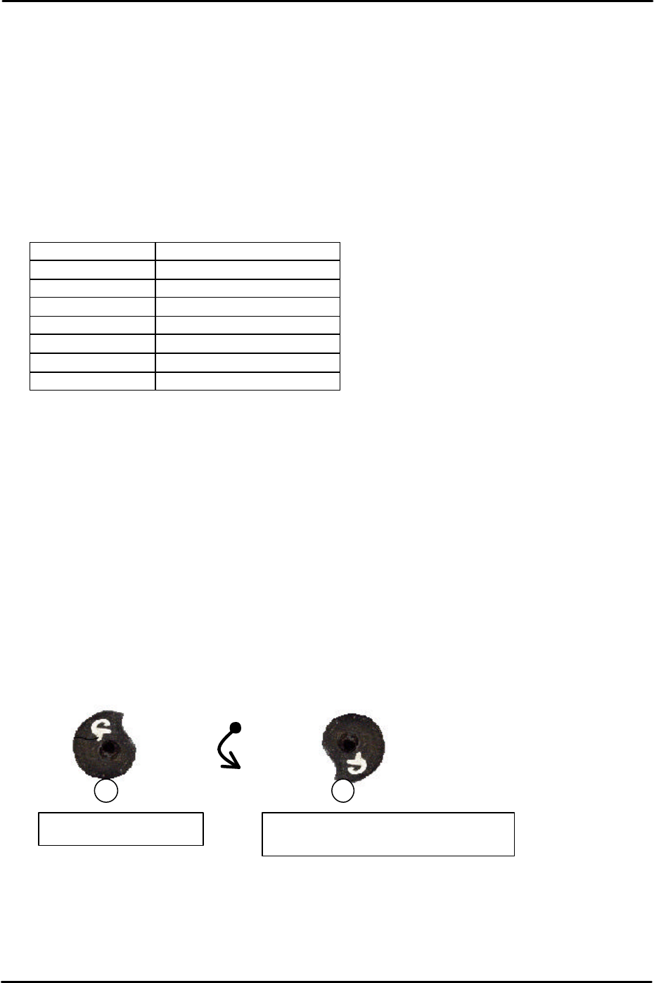
2. To set the F and G axis minus limits set the cam at the upper resting position and then
rotate anti-clockwise until the cam is at the position just before it flips over the roller, this
is known as the lower resting position.
3. At this position select [Maintenance C] – [Proper Data Editor] – [Servo Limit] – [Minus
limit F/Minus limit G] – [Direct Servo Input] to save the current counter value to proper
data.
Counterclockwise
rotation
Upper resting position
Lower resting position (Minus Limit)
FK-9F98-29 XP Series Training Text for Service Engineers
Edition 5.0 XP141 – Chapter 2 Zero settings Page 4 of 4
Fuji Machine Mfg. Co., Ltd. Okazaki
SMT Equipment Quality Assurance Dept.
2 – 4 CS Section
2.5 Setting the plus software limits
1. Press the emergency stop button to cut the 200-volt power supply to the servos.
2. Set the X, Y and Z axes against the plus mechanical stoppers.
3. Select [Maintenance C] – [Proper Data Editor] – [Servo Limit] – [Plus limit X/Plus limit
Y/Plus limit Z] – [Direct Servo Input].
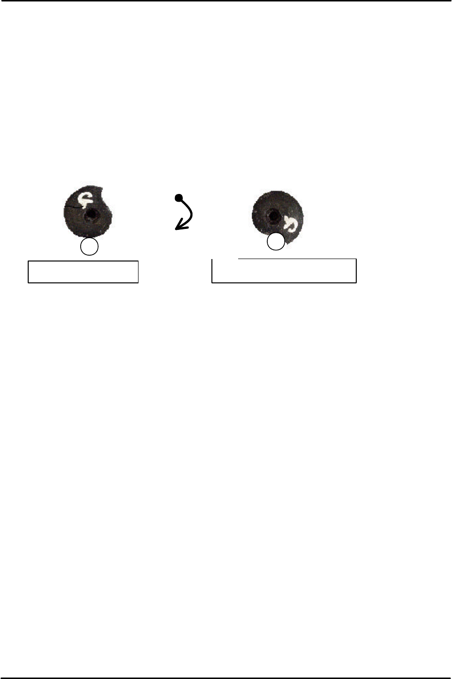
4. To set the F and G axis plus limits set the cam at the upper resting position and then
rotate clockwise until the cam contacts the roller and cannot rotate any further.
5. At this position select [Maintenance C] – [Proper data editor] – [Servo Limit] – [Plus limit
F/Plus limit G] – [Direct servo Input] to save the current counter value to proper data.
Upper resting position
Upper limit resting position
Clockwise rotation

C
C
h
h
a
a
p
p
t
t
e
e
r
r
3
3
S
S
t
t
a
a
t
t
i
i
c
c
A
A
c
c
c
c
u
u
r
r
a
a
c
c
y
y
M
M
e
e
a
a
s
s
u
u
r
r
e
e
m
m
e
e
n
n
t
t