xp141-241-341-5.0E.pdf - 第22页
C C h h a a p p t t e e r r 3 3 S S t t a a t t i i c c A A c c c c u u r r a a c c y y M M e e a a s s u u r r e e m m e e n n t t
FK-9F98-29 XP Series Training Text for Service Engineers
Edition 5.0 XP141 – Chapter 2 Zero settings Page 4 of 4
Fuji Machine Mfg. Co., Ltd. Okazaki
SMT Equipment Quality Assurance Dept.
2 – 4 CS Section
2.5 Setting the plus software limits
1. Press the emergency stop button to cut the 200-volt power supply to the servos.
2. Set the X, Y and Z axes against the plus mechanical stoppers.
3. Select [Maintenance C] – [Proper Data Editor] – [Servo Limit] – [Plus limit X/Plus limit
Y/Plus limit Z] – [Direct Servo Input].
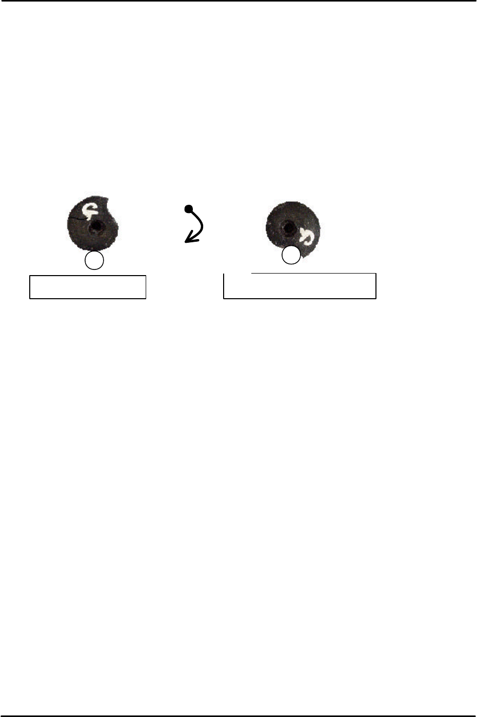
4. To set the F and G axis plus limits set the cam at the upper resting position and then
rotate clockwise until the cam contacts the roller and cannot rotate any further.
5. At this position select [Maintenance C] – [Proper data editor] – [Servo Limit] – [Plus limit
F/Plus limit G] – [Direct servo Input] to save the current counter value to proper data.
Upper resting position
Upper limit resting position
Clockwise rotation

C
C
h
h
a
a
p
p
t
t
e
e
r
r
3
3
S
S
t
t
a
a
t
t
i
i
c
c
A
A
c
c
c
c
u
u
r
r
a
a
c
c
y
y
M
M
e
e
a
a
s
s
u
u
r
r
e
e
m
m
e
e
n
n
t
t
FK-9F98-29 XP Series Training Text for Service Engineers
Edition 5.0 XP141 – Chapter 3 Static Accuracy Measurement Page 1 of 2
Fuji Machine Mfg. Co., Ltd. Okazaki
SMT Equipment Quality Assurance Dept.
3 – 1 CS Section
Chapter 3 – Static Accuracy Measurement
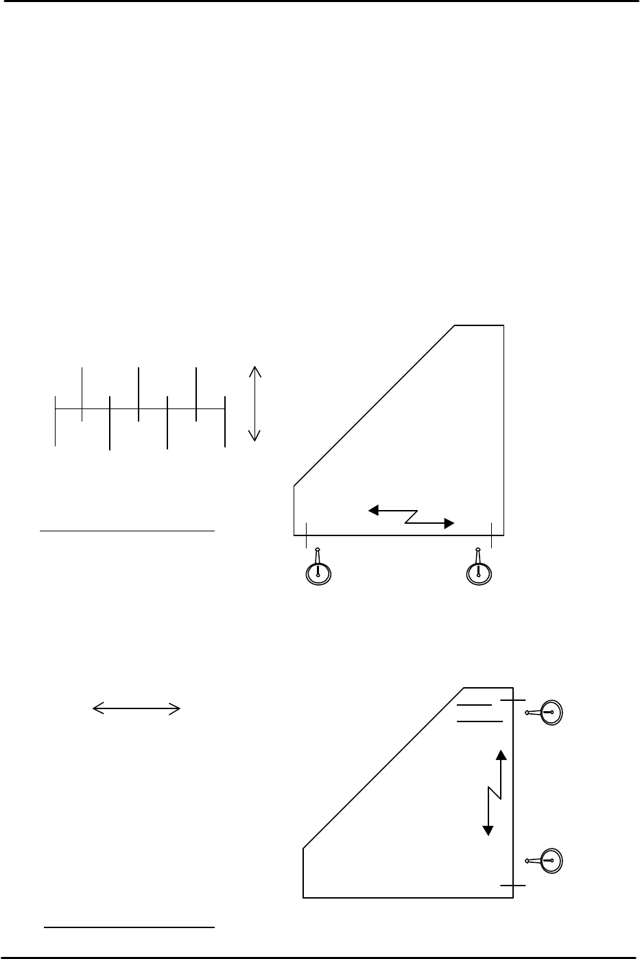
3.1 Checking the straightness of the X/Y axes
1. Equipment: perpendicular measurement jig (Z9531DEPJ0050). Lever type dial gage
(0.01mm).
2. Attach the dial gage to the placement head (an extension bar is necessary).
3. Place the perpendicular measurement jig (Z9531DEPJ0050) on to the conveyor. Adjust
the jig position so that when running the dial gage along the jig in the X direction, the
0mm and 300mm point values are both “0” (i.e. the jig is parallel to the X axis).
4. If the XY-axis squareness needs to be measured, it is better to perform measurement
(3.2) first, before measuring the Y-axis straightness.
5. Measure the Y axis straightness in the same way as the X-axis. Measure in the part
placement area of the main conveyor.
250 150 50
300 200 100 0
( ) ( ) ( )
0 ( ) ( ) ( )
+
–
Tolerance: 0.06/300 (mm)
0
0X-direction
Z9531DEPJ0050
300mm
point
0 point
Movement distance of the X-axis
0
( )
( )
( )
( )
( )
0
300
250
100
150
100
50
0
+ -
Movement distance of the Y-axis
0
0
Y-direction
Z9531DEPJ0050
Tolerance: 0.06/300 (mm)
300m
m point
0 point