xp141-241-341-5.0E.pdf - 第105页
C C h h a a p p t t e e r r 3 3 S S t t a a t t i i c c A A c c c c u u r r a a c c y y M M e e a a s s u u r r e e m m e e n n t t
FK-9F98-29 XP Series Training Text for Service Engineers
Edition 5.0 XP241 – Chapter 2 Zero Setting Page 4 of 4
Fuji Machine Mfg. Co., Ltd. Okazaki.
SMT Equipment Quality Assurance Dept.
2 – 4 CS Section
2.6 Setting the plus software limits
1. Set each axis to its plus mechanical stopper. Refer to
the mechanical stopper location diagrams in the
supplementary section of this manual.
Note: Press the emergency stop button to cut the
(200V) power supply to the servo when setting each of
the axes to the plus mechanical stopper.
Note: Take special precautions when using the [JOG]
key to set the T-axis to the Plus (+) mechanical
stopper position.
2. Select [MAINTENANCE C] – [Proper Data Editor] –
[Servo Limit].
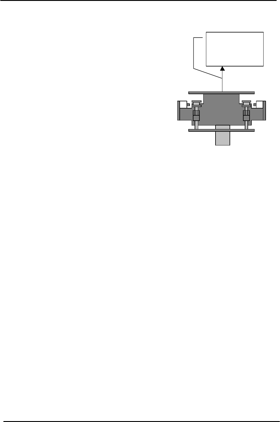
3. Select the “Plus Limit” proper item for the relevant axis and enter the counter value by
pressing the [Direct Servo Input] key.
Note: for the U-axis setting pull and hold the U shuttle against the plus mechanical
stopper (MTU Side), and then press the [Direct Servo Input] key.
The shuttle is
pulled towards
the MTU side.

C
C
h
h
a
a
p
p
t
t
e
e
r
r
3
3
S
S
t
t
a
a
t
t
i
i
c
c
A
A
c
c
c
c
u
u
r
r
a
a
c
c
y
y
M
M
e
e
a
a
s
s
u
u
r
r
e
e
m
m
e
e
n
n
t
t
FK-9F98-29 XP Series Training Test for Service Engineers
Edition 5.0 XP241 – Chapter 3 Static Accuracy Measurement Page 1 of 6
Fuji Machine Mfg. Co., Ltd. Okazaki
SMT Equipment Quality Assurance Dept.
3 – 1 CS Section
Chapter 3 Static Accuracy Measurement
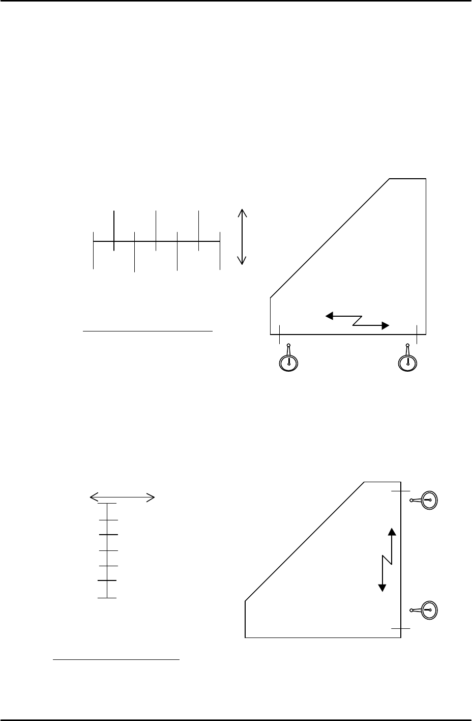
3.1 Checking the straightness of the X/Y axes
• Jig: Perpendicular measurement jig Z9531DEPJ0050.
• Equipment: Lever type dial gauge (0.01mm).
1. Attach the dial gauge to the placement head (an extension bar is necessary).
2. Place the perpendicular measurement jig (Z9531DEPJ0050) on to the main conveyor.
Adjust the jig position so that when running the dial gage along the jig in the X direction,
the 0mm and 300mm point values are both 0 (i.e. the jig is parallel to the X axis).
Note: If the XY-axis squareness needs to be measured, it is better to perform
measurement (3.2) first, before measuring the Y-axis straightness.
3. Measure the Y-axis straightness in the same way as the X-axis.
Note: measure in the part placement area of the main conveyor.
250 150 50
300 200 100 0
( ) ( ) ( )
0 ( ) ( ) 0
+
-
Tolerance: 0.06/300 (mm)
0 0X-direction
Z9531DEPJ0050
300mm
point
0 point
Movement distance of the X-axis
0
( )
( )
( )
( )
( )
0
300
250
100
150
100
50
0
+ -
Movement distance of the Y-axis
0
0
Y-direction
Z9531DEPJ0050
Tolerance: 0.06/300 (mm)
300mm
point
0 point