xp141-241-341-5.0E.pdf - 第178页
FK-9F98- 29 XP Series Training Text for Service Engineers Edition 5.0 XP241 – Chapter 8 Options Page 6 of 10 Fuji Machine Mfg. Co., Ltd. Okazaki SMT Equipment Quality Assurance Dept. 8 – 6 CS Section Proper Setting 1. Se…
FK-9F98-29 XP Series Training Text for Service Engineers
Edition 5.0 XP241 – Chapter 8 Options Page 5 of 10
Fuji Machine Mfg. Co., Ltd. Okazaki
SMT Equipment Quality Assurance Dept.
8 – 5 CS Section
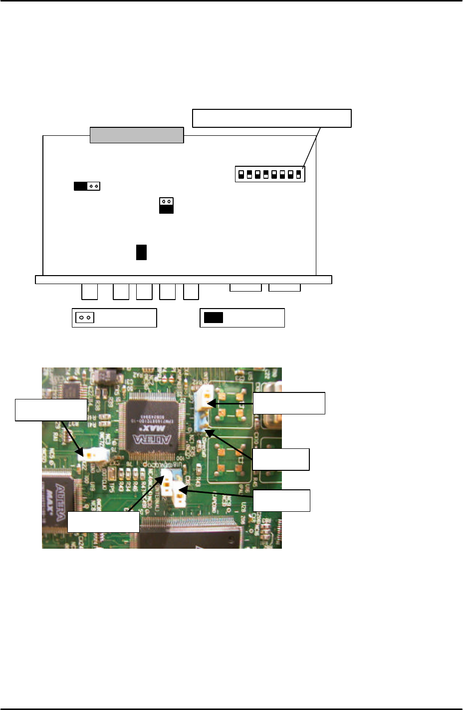
Vision Board Setting
1. Before proceeding with this setting make sure that the machine power and breaker are
OFF.
2. In order to set the vision board jumpers for use with the coplanarity check camera please
refer to the following illustration and picture:
3. It is necessary to remove the Vision board from the rack in order to set the jumpers. The
CPU board and vision boards are joined, so they must be removed together.
4. Ensure that JP2 is set to short and that JP3 is set to OPEN.
S1
.1
S1
.2
S1
.3
S1
;4
S1
.5
S1
.6
S1
.7
S1
.8
ONJP7 JP6
JP3
JP2
JP5
The dipswitch position is shown in black
Open Short
For details of the location of
the vision board please refer
to the VME rack
configuration diagram in the
supplementary information
section of this manual
JP6 is open
JP7 is shorted
JP3 is open
JP2 is shorted
JP5 is shorted
Note that the
orientation of this
picture is different to
that of the diagram
above
FK-9F98-29 XP Series Training Text for Service Engineers
Edition 5.0 XP241 – Chapter 8 Options Page 6 of 10
Fuji Machine Mfg. Co., Ltd. Okazaki
SMT Equipment Quality Assurance Dept.
8 – 6 CS Section
Proper Setting
1. Select [Maintenance C] – [Proper Data Editor] – [Machine_Type] and set “_Coplanarity”
to “1”.
2. Select [Maintenance C] – [Proper Data Editor] – [Others] and temporarily set
“_CoplaCamShutterSpeed” to “3000”.
Camera position
1. Set the coplanarity camera nozzle jig in position 1 of the nozzle change station.
2. Select [Production] – [Nozzle Editor] and set the nozzle size for position 1. Note that any
size is okay as long as the setting is not “Empty”.
3. Select [Manual Operation] – [Nozzle Operation] – [1] – [Execute] – [START] and pick up
the coplanarity camera nozzle jig from the nozzle change station.
4. Select [Maintenance C] – [Proper Data Editor] – [Others] and set the following proper
data items:
X_CoplanarityPosX 645
Y_CoplanarityPosY Here input the “_PrismBack” value input in chapter 6.6
Z_CoplanarityPosZ 43.7
5. Select [Maintenance A] – [Jog] and bring the X and Y axes to the positions input in step
4.
6. Once the positions of the X and Y-axes have been set, bring the Z-axis to 43.7mm.
7. Select the coplanarity camera and display the cross hairs on the screen.
8. The coplanarity camera jig should be visible. Temporarily set the focus of the coplanarity
camera by turning the focus ring on the end of the lens.
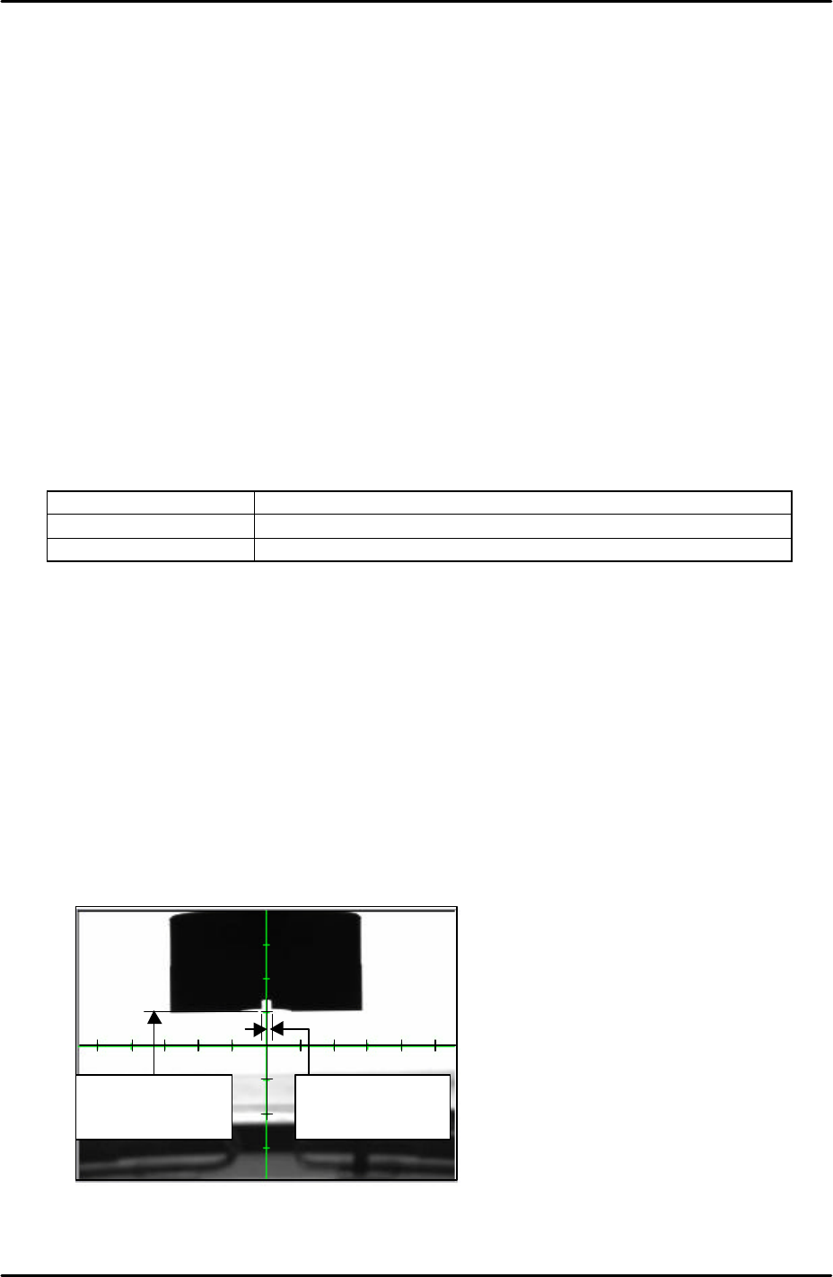
9. Adjust the position of the camera bracket so that the vertical cross hair is in the center of
the hole in the coplanarity camera nozzle jig. Please see the picture below:
5 memory scales
from the horizontal
cross hair
Vertical cross hair is
in the center of the
nozzle jig
FK-9F98-29 XP Series Training Text for Service Engineers
Edition 5.0 XP241 – Chapter 8 Options Page 7 of 10
Fuji Machine Mfg. Co., Ltd. Okazaki
SMT Equipment Quality Assurance Dept.
8 – 7 CS Section
10. Adjust the coplanarity camera tilt using the tilt adjusting bolt on the camera bracket.
11. The position of the camera should be adjusted so that the bottom edge of the jig is
aligned five memory scales above the horizontal cross hair. Please see the picture
below:
12. Once the camera position has been set lock all the bolts and confirm that the position
does not change.
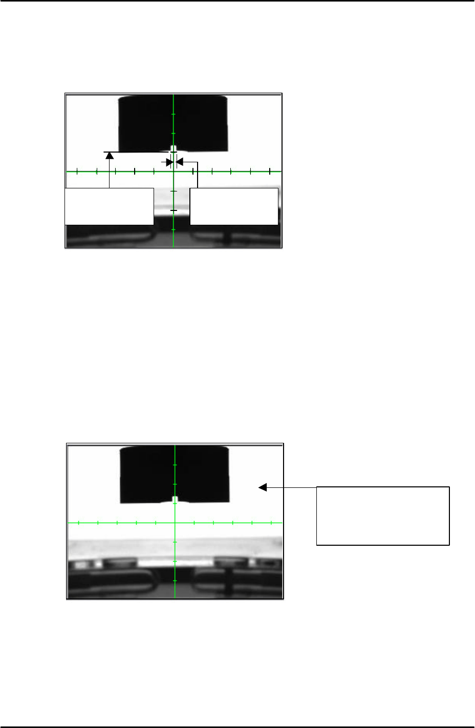
Camera focus and brightness
1. Adjust the camera focus so that the corner edges of the coplanarity camera nozzle jig are
as clear and sharp as possible. Adjust the focus by turning the focus ring on the end of
the camera lens. Once the focus has been set lock the focus ring set bolt.
2. After setting the focus it is necessary to set the camera brightness. Touch the white
background on the monitor to get a brightness reading as shown below:
3. The brightness value should be 210 +/- 10. If not it is necessary to adjust the
“_CoplaCamShutterSpeed” value in proper data, this has already been set to 3000 by
default. Select [Maintenance C] – [Proper Data Editor] – [Others] –
[CoplaCamShutterSpeed] and adjust the value. Lowering the value will decrease the
coplanarity camera brightness, and raising the value will increase the brightness.
4. Continue editing the value until the brightness reading is 210 +/-10.
5 memory scales
from the horizontal
cross hair
Vertical cross hair is
in the center of the
nozzle jig
Touch anywhere in the
white background to
display a brightness
reading