xp141-241-341-5.0E.pdf - 第25页
C C h h a a p p t t e e r r 4 4 L L o o a a d d e e r r A A d d j j u u s s t t m m e e n n t t
FK-9F98-29 XP Series Training Text for Service Engineers
Edition 5.0 XP141 – Chapter 3 Static Accuracy Measurement Page 2 of 2
Fuji Machine Mfg. Co., Ltd. Okazaki
SMT Equipment Quality Assurance Dept.
3 – 2 CS Section
3.2 Measuring the squareness of the XY axis
1. Equipment: perpendicular measurement jig (Z9531DEPJ0050). Lever type dial gage
(0.01mm).
2. Load the perpendicular measurement jig on the conveyor, and position it so that the X-
side is parallel with the X-axis.
3. With the jig in this position, measure the Y-direction side. This indicates the Y-axis
orientation that is perpendicular to the X-axis.
4. Measure in the part placement area of the main conveyor.
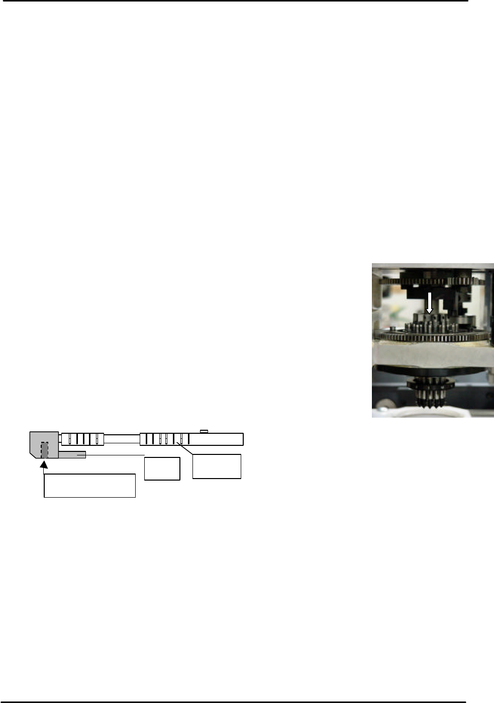
3.3 Measuring the piston deviation
1. Equipment: lever type dial gage (0.01mm).
2. Bring the number 1 nozzle to the front of the machine and set the
dial gage on the top of the nozzle piston as indicated in the adjacent
picture:
3. Using the number 1 nozzle piston height as a reference, move the R
axis through one rotation and measure all the remaining pistons.
4. The height difference between the highest and lowest piston should
be within 0.10mm. If out of tolerance please contact FUJI.
5. If one of the pistons is removed for any reason, apply low strength
adhesive (Loctite 222) to the cap bolt to prevent loosening. In
addition, apply AFC grease to the piston.
3.4 Measuring the backlash
1. Equipment: lever type dial gage (0.002mm).
2. With the servo ON set the dial gage against the X and Y axes in turn and measure the
backlash.
3. Any backlash should be within 0.01mm.
4. In the case of the Q and R axis gears there should be no backlash.
Piston
Pin
Hex cap bolt

C
C
h
h
a
a
p
p
t
t
e
e
r
r
4
4
L
L
o
o
a
a
d
d
e
e
r
r
A
A
d
d
j
j
u
u
s
s
t
t
m
m
e
e
n
n
t
t
FK-9F98-29 XP Series Training Text for Service Engineers
Edition 5.0 XP141 – Chapter 4 Loader Adjustment Page 1 of 12
Fuji Machine Mfg. Co., Ltd. Okazaki.
SMT Equipment Quality Assurance Dept.
4 – 1 CS Section
Chapter 4: Loader Adjustment
4.1 Measuring the Flatness of the Lifter Plate
• Measuring equipment: standard lever type dial gauge (0.01mm).
1. Adjust the conveyor to its maximum width
(356mm), and then remove the back-up plate.
Note: Do not use the conveyor auto width
changer, as this is not adjusted yet.
2. Loosen the lock nuts on the clamper height
adjustment bolts.
3. Raise the main lifter.
Note: There should be some clearance between the
lifter plate and clamper height adjustment bolts. If there is no clearance between them screw
the clamper height adjustment bolts in to achieve clearance.
4. Attach the dial gauge to the placing head (an
extension bar is necessary).
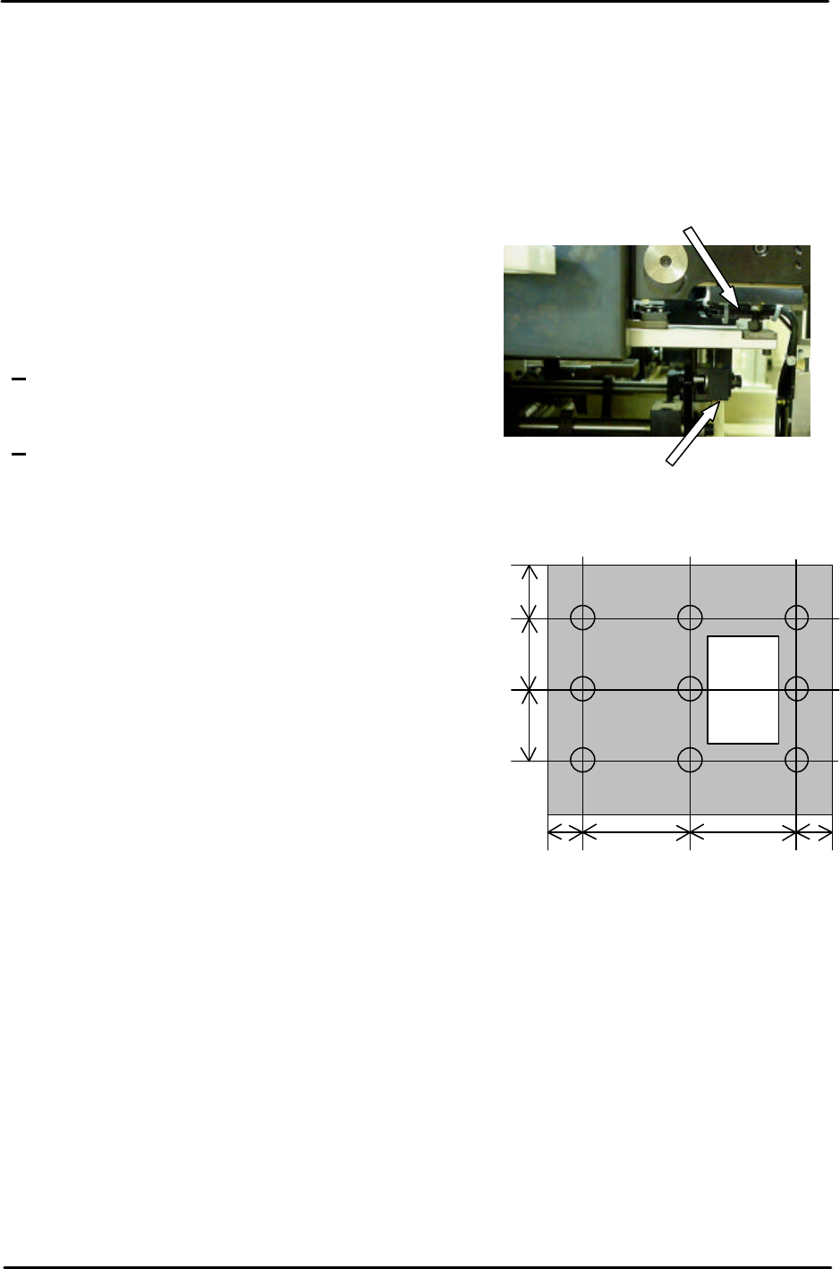
Measure the Four Corners of the table
(Points: A, C, G, and I); ensure each value is
0. If the table is not flat, re-adjust it using the
four height adjustment bolts.
5. After ensuring the four-corners of the table are
flat, measure the surface of the table at the
nine positions shown in the diagram. Any
deviation should be within 0.10mm. If the
values are out of tolerance please contact
FUJI.
4.2 Measuring the Flatness and Parallelism of the Fixed Rail
Parallelism of the Fixed Rail
• Measuring equipment: standard lever type dial gauge (0.01mm).
1. Attach the dial guage to the placing head (an extension bar is necesarry).
2. Set the dial gauge to the reference side of the conveyor.
3. Set the dial gage to “0”. Measure the parallelism of the fixed rail.
4. Record your measurements on the adjustments check sheet:
Height adjustment bolt
Clamper height adjustment bolt
I H G
F E D
C B A
180 180 5050
80
110
110