xp141-241-341-5.0E.pdf - 第130页
FK-9F98- 29 XP Series training Text for Service Engineers Edition 5.0 XP241 – Chapter 5 Peripheral Adjustments Page 5 of 19 Fuji Machine Mfg. Co., Ltd. Okazaki. SMT Equipment Quality Assurance Dept . 5 – 5 CS Section Tra…

FK-9F98-29 XP Series training Text for Service Engineers
Edition 5.0 XP241 – Chapter 5 Peripheral Adjustments Page 4 of 19
Fuji Machine Mfg. Co., Ltd. Okazaki.
SMT Equipment Quality Assurance Dept.
5 – 4 CS Section
Output timer changeover switch OFF
Output changeover switch L.ON
FINE/TURBO toggle switch FINE
5. Push the [LOCK] switch down to unlock the amplifier.
6. With the sensor uninterrupted press the [SET] button once.
7. With the sensor interrupted press the [SET] button one more time.
8. Push the [LOCK] switch up to lock the amplifier.
9. To monitor the status of the sensor select [Maintenance A] – [I/O Check] – [X03C
TraySetCheck].
10. To check the position of the sensor use the MTU Interlock Sensor Jig (Z9631DEPJ3101).
This slides into the MTU like a tray and has two protrusions at either end, one of 2.5mm,
one of 3.5mm.
11. With the 2.5mm protrusion foremost slide the jig into the tray position selected at step 2.
The jig should be pushed in as far as it will go so that it is in contact with the MTU guide
bar rail.
12. Under these conditions the sensor [X03C TraySetCheck] should be ON.
13. With the 3.5mm protrusion foremost slide the jig into the tray position selected at step 2.
The jig should be pushed in as far as it will go so that it is in contact with the MTU guide
bar rail.
14. Under these conditions the sensor [X03C TraySetCheck] should be OFF.
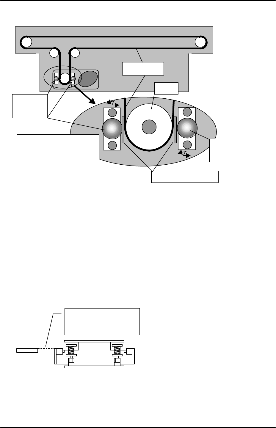
U-axis belt slippage adjustment
1. Use a feeler gauge and adjust the roller guide so that the distance between the roller and
the belt becomes 0.1 mm.
2. Insert a 0.1mm feeler gauge between the pully belt and roller. Lightly push the roller
against the pulley and tighten the roller bolt.
FK-9F98-29 XP Series training Text for Service Engineers
Edition 5.0 XP241 – Chapter 5 Peripheral Adjustments Page 5 of 19
Fuji Machine Mfg. Co., Ltd. Okazaki.
SMT Equipment Quality Assurance Dept.
5 – 5 CS Section
Tray shuttle advance / retract adjustment
1. Select [Manual Operation] – [Tray Operation] – [Tray Exchange Pos.] – [START] to move
the tray unit to the tray exchange position.
2. Retract the shuttle, making sure it moves to its retract position.
3. Descend the magazine so that the rollers on the U-axis shuttle are visible.
4. Ensure that the shuttle rollers and the T-axis guide bars are in alignment. If they are not
in alignment, adjust the shuttle retract position by editing [Maintenance C] – [Proper Data
Editor] – [Tray] – [U_Shuttle Backward Ofst].
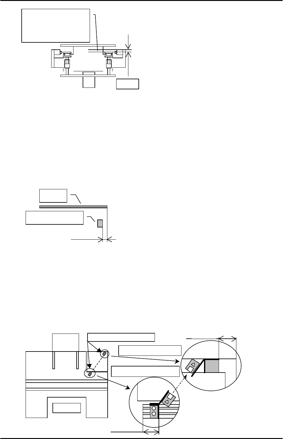
5. When the shuttle is at the retract limit position (under 200v ON condition), the clamper
should be 0.5mm inside the roller. See diagram overleaf.
Roller for
slippage
prevention
Pulley
0.1mm feeler gauge
Roller for
slippage
prevention
Insert the feeler gauge
between the pulley and roller.
Push the roller against the
pulley and tighten the bolt.
Timing belt
The shuttle roller and the
guide bar should be in
alignment.
Guide bar
FK-9F98-29 XP Series training Text for Service Engineers
Edition 5.0 XP241 – Chapter 5 Peripheral Adjustments Page 6 of 19
Fuji Machine Mfg. Co., Ltd. Okazaki.
SMT Equipment Quality Assurance Dept.
5 – 6 CS Section
6. Select [Manual Operation] – [Tray Operation] - [Tray Exchange Pos.] – [START].
7. Mount a tray at tray position 01, and set the T axis to the T_Tray Org position.
Warning: ensure the shuttle and the tray do not collide when the tray unit is at its lower
limit.
8. Select [Manual Operation] – [Tray Operation] – [Advance Shuttle] to advance the shuttle.
9. Adjust the tray advance limit sensor so that it is 5 mm from the front of the tray.
Ensure that the I/O X039 P.PosTrayDetect turns OFF when the tray is advanced.
Note: Set the arrival sensor amplifier to its maximum.
10. Ensure the conveyance of the trays works properly at all positions from 01 to 91.
Adjusting the tray eject check sensor
1. Select the I/O Input “X02A TrayPickUpChk”, and, adjust the sensor positions so that they
can detect ejected trays. The movable side sensor bracket can be slid along an
aluminium rail. The bracket should be positioned 35mm from the end of the rail. Please
see the diagram below:
Adjust so that the clamper
is positioned 0.5mm inside
the roller.
0.5mm
5mm
Arrival check sensor
Tray
M/C front
MTU
Tray eject check sensor
35mm
Movable side sensor BKT
Fixed side sensor BKT
30.5mm