xp141-241-341-5.0E.pdf - 第19页
FK-9F98- 29 XP Series Training Text for Service Engineers Edition 5.0 XP141 – Chapter 2 Zero settings Page 2 of 4 Fuji Machine Mfg. Co., Ltd. Okazaki SMT Equipment Quality Assurance Dept. 2 – 2 CS Section 3. Set the Q, R…

FK-9F98-29 XP Series Training Text for Service Engineers
Edition 5.0 XP141 – Chapter 2 Zero settings Page 1 of 4
Fuji Machine Mfg. Co., Ltd. Okazaki
SMT Equipment Quality Assurance Dept.
2 – 1 CS Section
Chapter 2 – Zero Settings
2.1 Checking the digital amplifier parameters
1. Equipment: digital operator (JUSP-0P02A).
2. Press the emergency stop button to cut the 200-volt power supply to the servos.
3. Connect the digital operator to the relevant servo amplifier, (“bb” displays at the screen).
4. Press [DSPL/SET] to select the channel mode (Pn000).
5. Specify the number of the channel to be checked, then press [DATA/ENTER] to display.
6. Ensure that the values match those listed in the servo amp parameter list.
7. When you have completed checking the parameters, return to the “bb” screen.
8. If any of the servo parameter values are changed, the machine must be rebooted before
continuing with adjustments.
9. If the “multiturn” limit parameter Pn205 is changed “A.CC” will display on the amp. In this
case connect a digital operator to the amp.
10. Press the M/C emergency stop button and then release it.
11. Press [DSPL/SET] and select channel Fn000.
12. Press the up key to select channel Fn013.
13. Press [DATA/ENTER] to display [PGSET].
14. Press [DSPL/SET] and (done) displays for one second.
15. Return to Fn000 and press [DSPL/SET] to return to the initial screen, which will still
display “A.CC” until the machine is rebooted.
16. Reboot the machine and confirm that “bb” or “run’ displays on the amp.
2.2 Setting the servo amp defaults
1. Equipment: digital operator (JUSP-OPO2A).
2. Press the emergency stop button to cut the 200-volt power supply to the servos, then
set the X, Y and Z axes to their minus mechanical stoppers. For details of the location of
mechanical stoppers please refer to the diagrams in the “Supplementary Information”
section of this manual.

FK-9F98-29 XP Series Training Text for Service Engineers
Edition 5.0 XP141 – Chapter 2 Zero settings Page 2 of 4
Fuji Machine Mfg. Co., Ltd. Okazaki
SMT Equipment Quality Assurance Dept.
2 – 2 CS Section
3. Set the Q, R, G and F axes at the following positions:
Q axis origin
The pusher should be facing out towards the front of the machine.
R-axis origin
Nozzle No.1 should be facing out towards the front of the machine.
G/F axis origin
The cam for the tape-indexing lever should be at its upper resting position.
4. Press the emergency stop button so that the 200-volt power supply to the servos cuts
out.
5. Connect the digital operator to the target servo amp, (“bb” is displayed on the screen).
6. Press [DSPL/SET] to select the channel mode (Fn000).
7. Select channel (Fn008) by pressing the [UP] key.
8. Press [DATA/ENTER] to display “PGCL1”.
9. Press [UP] to set it to “PGCL5”.
10. Press [DSPL/SET] and “Done” displays.
11. Press [DATA/ENTER] to return to the support mode (Fn008).
12. Press [DOWN] to return to the channel mode (Fn000).
13. Press [DSPL/SET] to return to the initial screen (”bb’ or “run” displays).
14. Once the settings are complete select [Maintenance C] – [Proper Data Editor] –
[SERVO_OFST] and set the target offsets for all the axes to 0.
15. Shut down and restart the machine.
2.3 Setting the origins
1. Select [Maintenance A] – [Jog]. The counter values should be on the screen. If the
values do not appear press the START button, or failing this reboot the machine.
2. Press the emergency stop button to cut the 200-volt power supply to the servos.
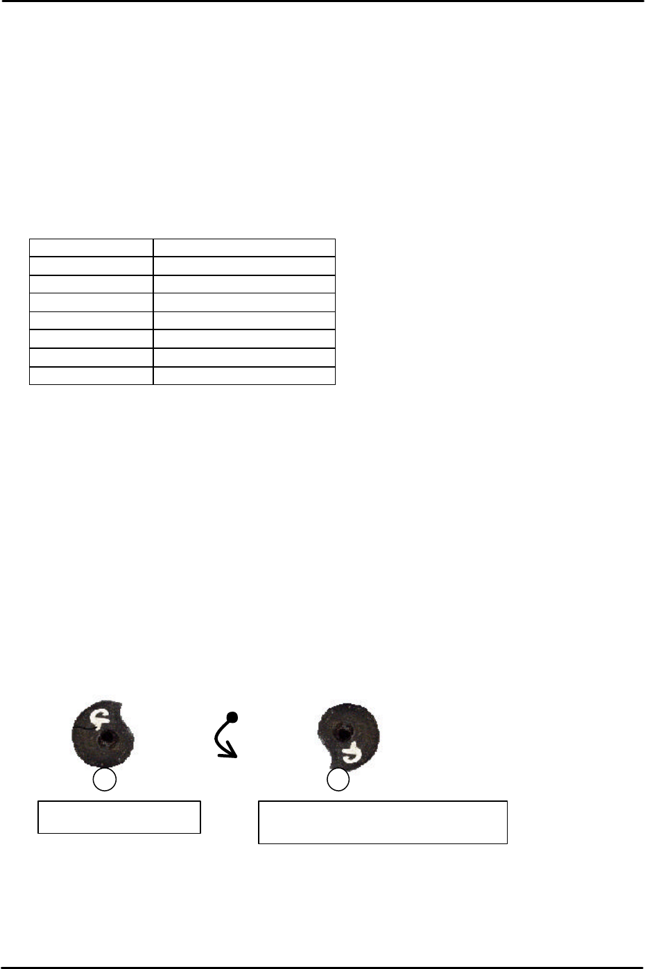
Fig. 2Fig. 1
When releasing the index cam from the
position in Fig.1, it stops at the position in
fig.2. This is the upper resting position.
FK-9F98-29 XP Series Training Text for Service Engineers
Edition 5.0 XP141 – Chapter 2 Zero settings Page 3 of 4
Fuji Machine Mfg. Co., Ltd. Okazaki
SMT Equipment Quality Assurance Dept.
2 – 3 CS Section
3. Confirm that the X, Y and Z axes are against the minus mechanical stoppers and that the
other axes are at their origin positions as described in (2.2).
4. Select [Maintenance C] – [Proper Data Editor].
5. Ensure “0” is set at the proper data item “Target Ofst”, for each axis.
6. Release the emergency stop button. Select [JOG] and record the counter value of each
axis except Q and R. Enter this value into the proper data item “target Ofst”.
Example: servo counter value is 18.252100(mm) – Input value 182521 (1/10 um).
7. Check that the target offsets are within the tolerance specified in the following table:
Target Offset Target Offset tolerance
Target Ofst X 0 +/- 320000
Target Ofst Y 0 +/- 500000
Target Ofst Z 0 +/- 200000
Target Ofst Q Enter 0 for the Q axis
Target Ofst R Enter 0 for the R axis
Target Ofst G 0 +/- 180000
Target Ofst F 0 +/- 180000
8. After making the target Ofst settings, select [Maintenance A] – [Jog] and ensure the
counter settings are close to “0”.
9. A counter value which is not close to “0” indicates that an inaccurate target Ofst has been
input. In this case input the target Ofst again.
2.4 Setting the minus software limits
1. Select [Maintenance C] – [Proper data editor] – [Servo Limit] and set the X, Y and Z axis
[minus limit] to “0”.
2. To set the F and G axis minus limits set the cam at the upper resting position and then
rotate anti-clockwise until the cam is at the position just before it flips over the roller, this
is known as the lower resting position.
3. At this position select [Maintenance C] – [Proper Data Editor] – [Servo Limit] – [Minus
limit F/Minus limit G] – [Direct Servo Input] to save the current counter value to proper
data.
Counterclockwise
rotation
Upper resting position
Lower resting position (Minus Limit)