JX-100_SPE_EN06.pdf - 第10页
6 4.1.1 Machine dimensions (mm) JX-100 JX-100 LED Dimensions Board transport height 900mm Board transport height 950mm Board transport height 900mm Board transport height 950mm A 1 170 B 900 950 900 950 C 1270 D 1060 1 1…
5
4. SPECIFICATIONS
4.1 Mechanical/Electrical Specifications
JX-100
Voltage 3-phase, 200V/220V/240V/380V/400V/415V AC (see Note 1)
Frequency 50/60 Hz
Power supply
Rated apparent power 1.5 kVA
Compressor supply
air pressure
0.6MPa to 0.9Mpa, Dry air (see Note 2)
Air pressure 0.5±0.05 Mpa Dry air (see Note 2)
345L/min(ANR), (see Note 3)
Air supply
Maximum air
consumption
50 L/min (ANR)
See Note 3 when the vacuum pump (option) is used
During operation
Ambient temperature +5ºC to +35ºC (Accuracy guaranty temperature: +20 to +25ºC)
Humidity 50 % RH or less (35ºC)
During transportation or storage
Temperature -15ºC to +70 ºC
Environment
requirements
Humidity 20% to 95% (No condensation)
Noise 75 dB (A) or less (see Note 4)
Installation place
Install this machine on a flat floor having a sufficient strength, such as
reinforced concrete floor.
Do not install this machine on a floor where the machine vibrates
during operation or on a wooden floor.
Particle dust
Do not install this machine in a place where a large amount of dust or
dirt exists.
Do not install this machine in a place close to a unit that produces the
high-frequency wave.
Power shut-down
Before turning OFF the main power, stop the machine and shut down
the system completely.
Additionally, if the main power is turned OFF while the SSD access
lamp is lit, this may cause the machine to malfunction. Do not turn
OFF the main power while the production is being carried out or an
axis is moving.
Note 1: An appropriate cross-sectional area of the primary power cable may vary depending on the
cable routing conditions, length, and/or power voltage. Always use an appropriate cable
meeting the standards for the installation place from those stated in the Table below.
Primary power cable
Power supply
Less than 20 m Less than 30 m Less than 40 m Less than 50 m
200V/220V/240V AC 5.5 mm
2
or more 5.5 mm
2
or more 8.0 mm
2
or more 10.0 mm
2
or more
380V/400V/415V AC 3.5 mm
2
or more 5.5 mm
2
or more 5.5 mm
2
or more 6.0 mm
2
or more
Note 2: Dry air: Always use an appropriate air dryer or mist separator. As for references, blow the
air to the metallic plate or other object at the compressor supply port to make sure that any
water droplets are not sticking to it.
Note 3: ANR: Temperature 20ºC, absolute pressure 0.1MPa (=100kPa =1 bar), and relative
humidity 65%
Note 4: Conforming to JIS Z 8731.
6
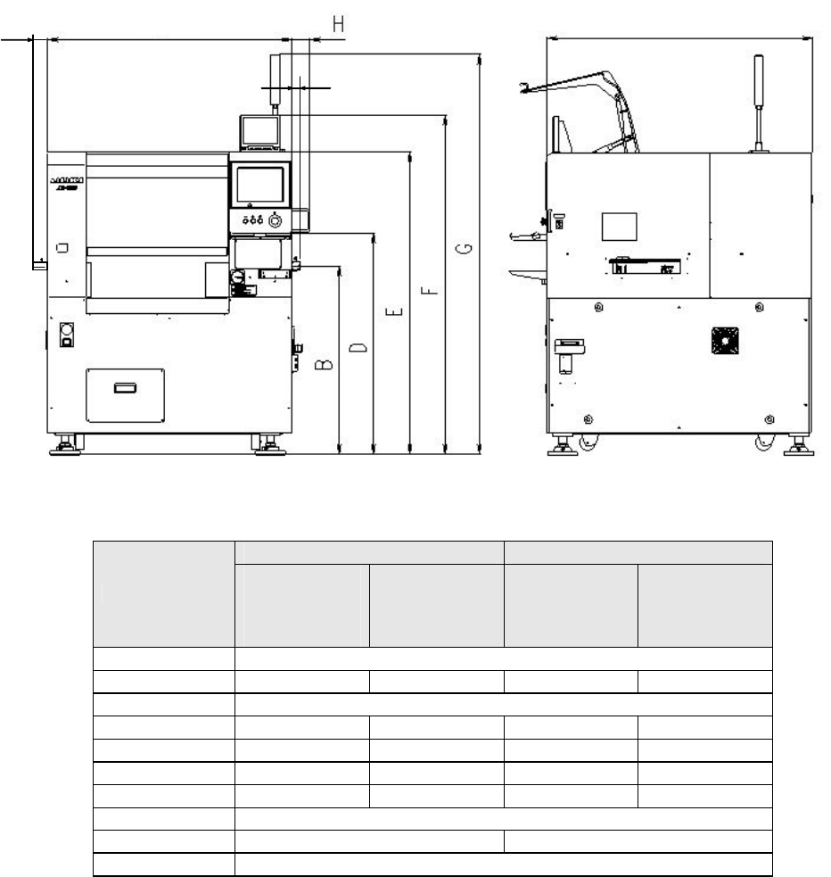
4.1.1 Machine dimensions
(mm)
JX-100 JX-100 LED
Dimensions
Board
transport
height
900mm
Board
transport
height
950mm
Board
transport
height
900mm
Board
transport
height
950mm
A 1170
B 900 950 900 950
C 1270
D 1060 1110 1060 1110
E 1440 1490 1440 1490
F 1620 1670 1620 1670
G 1910 1960 1910 1960
H 65
J 125(EN:130) 145(EN:150)
K 75(EN:80)
4.1.2 Mass
JX-100, JX-100 LED :1,000kg
J
K
C
A
4.2 Component placement Cycle Time (A Number of Components to Be
Placed Per Hour)
Laser recognition
15,300 CPH (conforming to IPC9850)
*1: This is a number of components to be placed for one hour when 400 1608 capacitors
are placed onto a 200 mm × 200 mm board at an angle of 0, 90, 180 and 270 degrees
sequentially.
*2: Simultaneous pickup and sequential placement of all the nozzles
*3
Conditions for placing the 0603 components: HMS (option for JX-100) is required. And the
system does not perform the simultaneous pickup but only the sequential pickup; the cycle
time is 10,300 CPH.
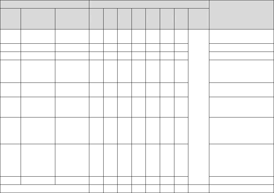
4.3 Nozzles
Various types of nozzles have been designed to increase the reliability of placement of
each type of components as shown in the table below.
For the standard attached nozzle, select from among the nozzles shown in the table below.
Table 1 Nozzles supplied as the standard devices
Nozzle Nozzle assembly
NO.
Internal
diameter of
a nozzle
External
diameter of
a nozzle
A B
E
F
G
H
J
Std.
nozzle
select
Applicable components
(reference)
500 2-φ0.4 1.0 x 0.5 - 6 - - - -
-
1005, 1608, 2012
* See Note 2
SOT (Molding: 1.6 x 0.8)
501 φ0.25 0.7 x 0.4 - - - - - -
-
0603 *See Note 3
502 φ0.4 φ0.7 6 - 3 - - 3
2
1005
503 φ0.6 φ1.0 6 - 6363
6
1608, 2012,
SOT (Molding: 1.6 x 0.8),
SOT (Molding: 2.0 x 1.25)
504 φ1.0 φ1.5 - 43663
4
2012, 3216, MELF, SOT23,
SOT (Molding: 2.0 x 1.25)
505 φ1.7 φ3.5 1 2 3 3 1 3
2
Aluminum electrolytic
capacitor (small), tantalum
electrolytic capacitor, trimmer
506 φ3.2 φ5.0 1 1 1 3 1 3
1
Aluminum electrolytic
capacitor (medium),
SOP (narrow type),
SOJ, Connector
507 φ5.0 φ8.5 1 1 - 111
1
Aluminum electrolytic
capacitor (large),
SOP (wide type),
TSOP, QFP, PLCC, SOJ,
Connector
508C φ8.0 φ9.5 1 1 1 1 1 1
1
*See
Note 1
QFP, PLCC, BGA
Total number of nozzles 16
15
17
17
16
17
17 16
* You can select a standard nozzle only.
* Total number of nozzles that can be installed onto an ATC station: 26. (There is not any
setting for a large type of nozzles.)
Note 1: For a Std. Nozzle Select, you can choose 15 nozzles from Nozzle No.500 to 508C.
However, a nozzle for machine calibration must be included in it.
One piece from among a No. 500, a No. 502 and a No. 503 nozzle to be
used for laser calibration
One piece of a No. 508C nozzle to be used for head offset
7