JX-100_SPE_EN06.pdf - 第35页
8.2.2 Input and Output Signal Interfaces Figure 14 Signal interfaces and connection terminals 8.2.3 Connection cable specifications A connection cable shall conform to the JIS B 8438 Industrial Robot – Electric Equipment…

8. INTERFACE
8.1 Mechanical Interface
Conveyor height
● 900 ±20 mm (Standard for Japan, China and Southeast Asia)
950 ±20 mm (Option for Europe and the U.S.A.)
、(Standard for EN machine only)
8.2 Electrical interfaces
8.2.1 Kinds and meanings of electrical signals
The conceptual diagram of the electrical signals both on the mounters and the other side
machines is shown in the following “Figure 11 Electrical signals connection conceptual
diagram “, as follows: The electrical signals between the mounters and upstream-side
devices ①, ② and between the mounters and downstream-side devices ③, ④ is
shown in the following diagram.
a) The electrical signal ① is called the “carryout request input signal (or PWBs
available-in),” receiving the PWBs carryout requests from the upstream-side devices.
b) The electrical signal ② is called the “carryout permit output signal (or ready-out),”
having the PWBs carried out to the upstream-side devices.
c) The electrical signal ③ is call the “carryout request output signal (or PWBs
available-out),” requesting the PWBs carryout to the downstream-side devices.
d) The electrical signal ④ is called the “carryout permit input signal (or
ready-in),“ receiving the PWBs carryout permits from the downstream-side devices.
Downstream-
side devices
Mounters
Upstream-
side devices
②
①
③
④
Figure 13 Electrical signals connection conceptual diagram
30
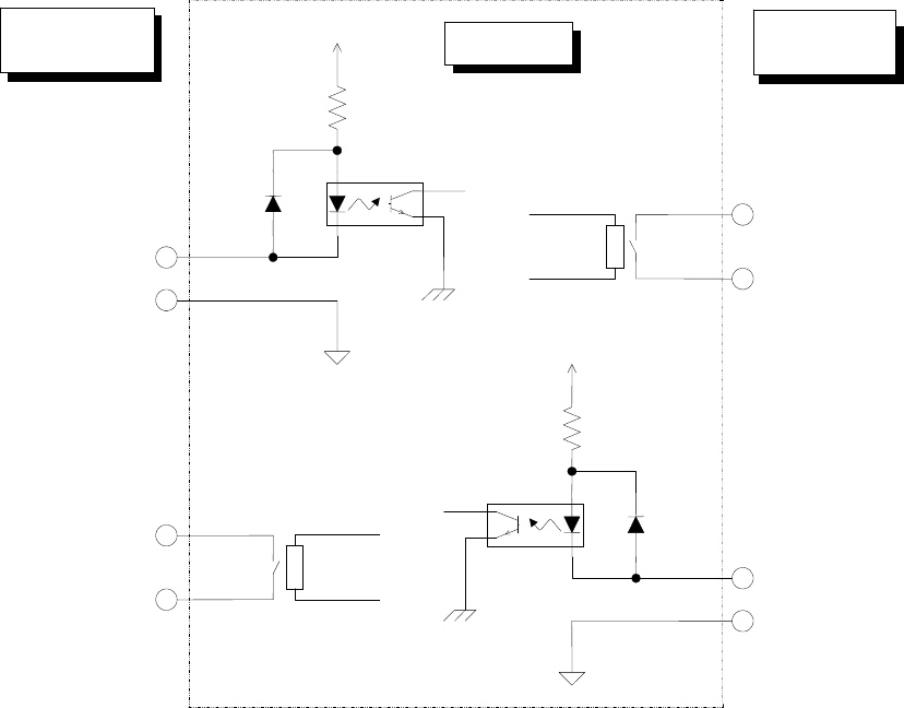
8.2.2 Input and Output Signal Interfaces
Figure 14 Signal interfaces and connection terminals
8.2.3 Connection cable specifications
A connection cable shall conform to the JIS B 8438 Industrial Robot – Electric Equipment.
The cable length shall be 10 m or less.
8.3 Data interface
● Equivalent to USB 2.0, two ports
● As data interfaces, FDD, DVD/CD-ROM, and others are connected. (USB connection,
option)
8.4 Utility Connections
● Piping joint
One-touch type piping joint plug for φ8 ×φ12
Pin No. 1 :
Carryout permit input signal
Pin No. 2 :
Carryout permit common signal
Relay contact point
Downstream-
side devices
Mounte
r
Upstream-
side devices
Pin No. 3 :
Carryout request output signal
Pin No. 4 :
Carryout request common signal
Pin No. 1 :
Carryout permit output signal
Pin No. 2 :
Carryout permit common signal
Pin No. 3 :
Carryout request input signal
Pin No. 4 :
Carryout request common signal
Relay contact point
+24V
+24V
31
9. SAFETY SPECIFICATIONS
9.1 Standards specifications
An emergency stop switch is provided in the front section. (However, when the rear bank
is selected as an option, another emergency stop switch is provided in the rear section.
When the emergency stop switch is pressed, each axis is stopped immediately and the
servo motor driving power supply is cut off (servo free status).
9.2 Safety covers
● A cover is provided at the front of the machine. When cover open/close status is
detected by cover open switch and the cover is opened, the machine is put in a servo
free status and stopped immediately. With the cover open, the machine cannot be
started.
● The EN machine has the "Switch key" used to switch between the two modes, the
"Maintenance mode" and the "Operation mode" on the operation panel, and the key is
used for the switching operation of the safety cover according to each mode.
・Operation mode
It usually controls the switching operation of the safety cover during the production.
The servomotor becomes free when the safety cover is opened.
・Maintenance mode
Low-speed operation becomes enabled when the safety cover is open. It is a mode
used for maintenance of the machine.
9.3 CE marking specifications (for EN machine)
This shall comply with the following EC (European committee) instructions
・EC Machinery Directive 2006/42/EC
・EC EMC Directive 2004/108/EC
Applicable standard
・Machinery Directive :
EN ISO12100-1:2003+A1:2009, EN ISO12100-2:2003+A1:2009,
EN ISO14121-1:2007, EN ISO13849-1:2008, EN60204-1:2006+A1:2009
・EMC Directive:
EN61000-6-4:2007, EN55016-1-2:2004, EN55016-2-1:2004,EN55016-2-3:2004,
EN61000-6-2-1:2005, EN61000-4-2-1:2009, EN61000-4-3:2006/A1:2008,
EN61000-4-4:2004, EN61000-4-5:2006, EN61000-4-6:2009,
EN61000-4-8:1993/A1:2001, EN61000-4-11:2004,
32