JX-100_SPE_EN06.pdf - 第4页
6. Optional f eeders .............................................................................................................. 1 9 6.1 Component suppl y met hod ......................................................…
TABLE OF CONTENTS
1. GENERAL ..........................................................................................................................1
2. FEATURES ........................................................................................................................1
3. SYSTEM CONFIGURATION .............................................................................................3
3.1 JX-100 System Configuration....................................................................................3
3.2 JX-100 LED System Configuration ............................................................................4
4. SPECIFICATIONS..............................................................................................................5
4.1 Mechanical/Electrical Specifications..........................................................................5
4.1.1 Machine dimensions ............................................................................................6
4.1.2 Mass....................................................................................................................6
4.2
Component placement Cycle Time (A Number of Components to Be Placed Per Hour).7
4.3 Nozzles......................................................................................................................7
4.4 Applicable Component...............................................................................................8
4.5 Component Placement Accuracy at X, Y and θ .........................................................8
4.6 Applicable PWBs.......................................................................................................9
4.6.1 PWBs transport direction .....................................................................................9
4.6.2 PWB sizes and Mass...........................................................................................9
4.6.3 Allowable value of board warp.............................................................................9
4.6.4 Limitations on PWBs............................................................................................9
4.6.5 PWBs clamping method.....................................................................................11
4.7 Function correcting the PWB positions....................................................................12
4.7.1 PWB positioning reference.................................................................................12
4.7.2 Field of vision for recognizing the PWB reference marks...................................12
4.7.3 Window size for recognizing the PWB reference marks.....................................12
4.7.4 Kinds of recognition marks and corrective method ............................................12
4.7.5 Shapes of each mark to be recognized..............................................................13
5. Standard Functions and Options..................................................................................16
5.1 Standard functions...................................................................................................16
5.1.1 Bad mark recognition.........................................................................................16
5.1.2 Liquid crystal touch panel
...................................................................................16
5.2 Options ....................................................................................................................16
5.2.1 Feeder floating detecting sensor (Option for the factory setting)........................16
5.2.2 Vacuum pump (Option for the factory setting)....................................................17
5.2.3 Height measuring function (HMS, option for the factory setting)........................17
5.2.4 Leakage breaker (Option for the factory setting)................................................17
5.2.5 Rear bank (Option for the factory setting)..........................................................17
5.2.6 Main line filter (Option).......................................................................................17
5.2.7 HOD (Option).....................................................................................................17
5.2.8 EPU (Option)......................................................................................................17
5.2.9 Air compressor Assembly (Option )....................................................................17
5.2.10 A simple Buffer (Option only for JX-100)..........................................................18
5.2.11
Lighting unit of solder recognition
(Option for the factory setting only for JX-100 LED)
...............................................18
6. Optional feeders..............................................................................................................19
6.1 Component supply method ...................................................................................... 19
6.2 Maximum Number of Types..................................................................................... 19
6.3 A List of Feeders...................................................................................................... 19
6.4 Tape Feeder ............................................................................................................ 20
6.4.1 CTF.................................................................................................................... 20
6.4.2 CTFR ................................................................................................................. 21
6.4.3 ATF .................................................................................................................... 22
6.4.4 FTF/FTFR ..........................................................................................................24
6.4.5 Adjustment jig for the feeder with a monitor ....................................................... 26
6.5 Tray Holder .............................................................................................................. 27
6.6 Stick Feeder............................................................................................................. 28
7. CONTROL SYSTEM SPECIFICATIONS..........................................................................29
7.1 Control ..................................................................................................................... 29
7.1.1 Program Selection..............................................................................................29
7.1.2 Limit of a production program ............................................................................29
7.2 Production mode......................................................................................................29
8. INTERFACE .....................................................................................................................30
8.1 Mechanical Interface................................................................................................30
8.2 Electrical interfaces.................................................................................................. 30
8.2.1 Kinds and meanings of electrical signals ........................................................... 30
8.2.2 Input and Output Signal Interfaces..................................................................... 31
8.2.3 Connection cable specifications......................................................................... 31
8.3 Data interface ........................................................................................................... 31
8.4 Utility Connections ................................................................................................... 31
9. Safety specifications.......................................................................................................32
9.1 Standards specifications.......................................................................................... 32
9.2 Safety covers ........................................................................................................... 32
9.3 CE marking specifications (for EN machine) ......................................................... 32
10. Maintenance Specifications...........................................................................................33
10.1 Troubleshooting ..................................................................................................... 33
10.2 Calibration function ................................................................................................ 33
10.3 MTBA Display Function.......................................................................................... 33
11. Reliability specifications................................................................................................33
11.1 Lifetime of devices ................................................................................................... 33
1
1. GENERAL
JX-100 is a new compact mounter specifically designed to be used alone with the
placement technology that is inherited from the KE and FX series. This machine has the
laser recognition unit LNC 60 and the 6 shafts on the head to place chip components.
The transportation system that can be switched between “Straight” and “U-turn” provides
flexibility for the cell manufacturing system.
JX-100 LED is a compact mounter upgrading JX-100 in a function, which is also suitable
for producing a longer PWB where LED chip component is placed.
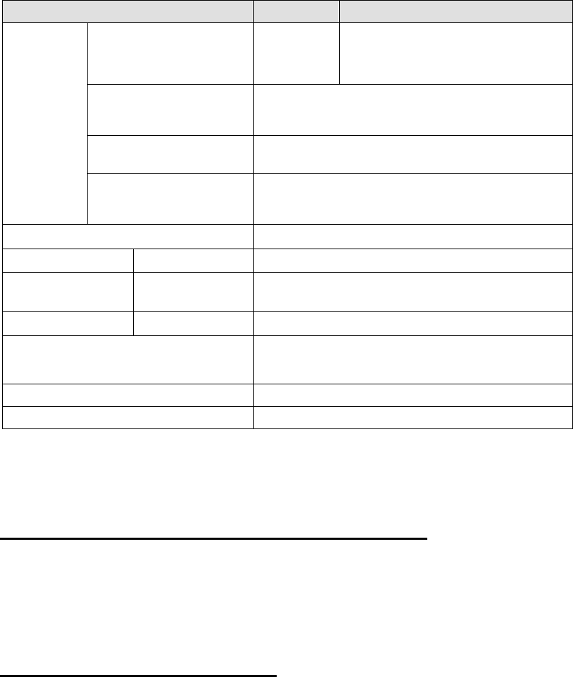
Model name JX-100 JX-100 LED
Board dimensions
Medium size
(330 × 250
mm)
Large size
(When fed once: 410 x 360 mm)
(When fed twice: 800 x 360 mm)
Direction in which a board
is transported
Left to Right, Right to Left
(The conveyor type can be switched between
"Straight" and "U-turn".)
Board transport reference
position
Only front reference
Board/
Transport
specification
Board transport height
900mm (Standard)
950mm (Option)
*EN Specification: 950mm only
Applicable component height NC(12mm)
Component size Laser recognition 0603 (see Note1)~□33.5mm
Placement speed
(CPH)
Chip component
(IPC9850)
15,300
Placement accuracy Laser recognition ±50μm (±3σ)
Number of component to be attached
Maximum 60 types (In 8 mm tape and when an
optional rear bank is used.)
Supported languages English, Japanese and Chinese
EN specifications Applicable
Note1
: HMS is required when a 0603 component is placed. (Option for JX-100 and Standard for
JX-100 LED )
2. FEATURES
High Precision and High Speed Placement of Components
① The high-speed placement of 15,300 CPH can be attained by a laser align sensor
(LNC60) that permits simultaneous recognition by 6-nozzle configuration
② An independent AC servo motor is used for an up/down operation (Z axis) of each
nozzle shaft and 2 AC servo motors are used for a rotating operation (θ axis) of each
nozzle shaft. This attains high-speed and high-accuracy placement without giving
any effect to the placement pattern.
Low Frequency of Failure Occurrence
① Since the laser heads monitor, via laser sensors, all the conditions of absorbing the
components, until right before completion of placement, it prevents a component from
dropping off.
② The function of self-calibrating the timing of releasing the vacuum pressure prevented
the components at a placement moment from being brought back.