JX-100_SPE_EN06.pdf - 第15页
11 Figure 4 Bottom surface view of PWB – Board size in X direction : 410 mm or more (3) Area w here component s can be placed on the PWB top side and bottom side. 部品 最 大 1 2 m m 最 大 2 0 m m 基板裏面 搭載可能範 囲 3mm 3mm Figure 5 …
10
(2) A range not available to set up the support pins
JX-100
はサポートピン設置不可範囲
5
0
~
2
5
0
m
m
50~330mm
3
2
m
m
60mm
10mm 基板サイズ320mm以上の時 10mm
4
m
m
4
m
m
8
~
1
0
5
m
m
基板幅による位置調整範囲
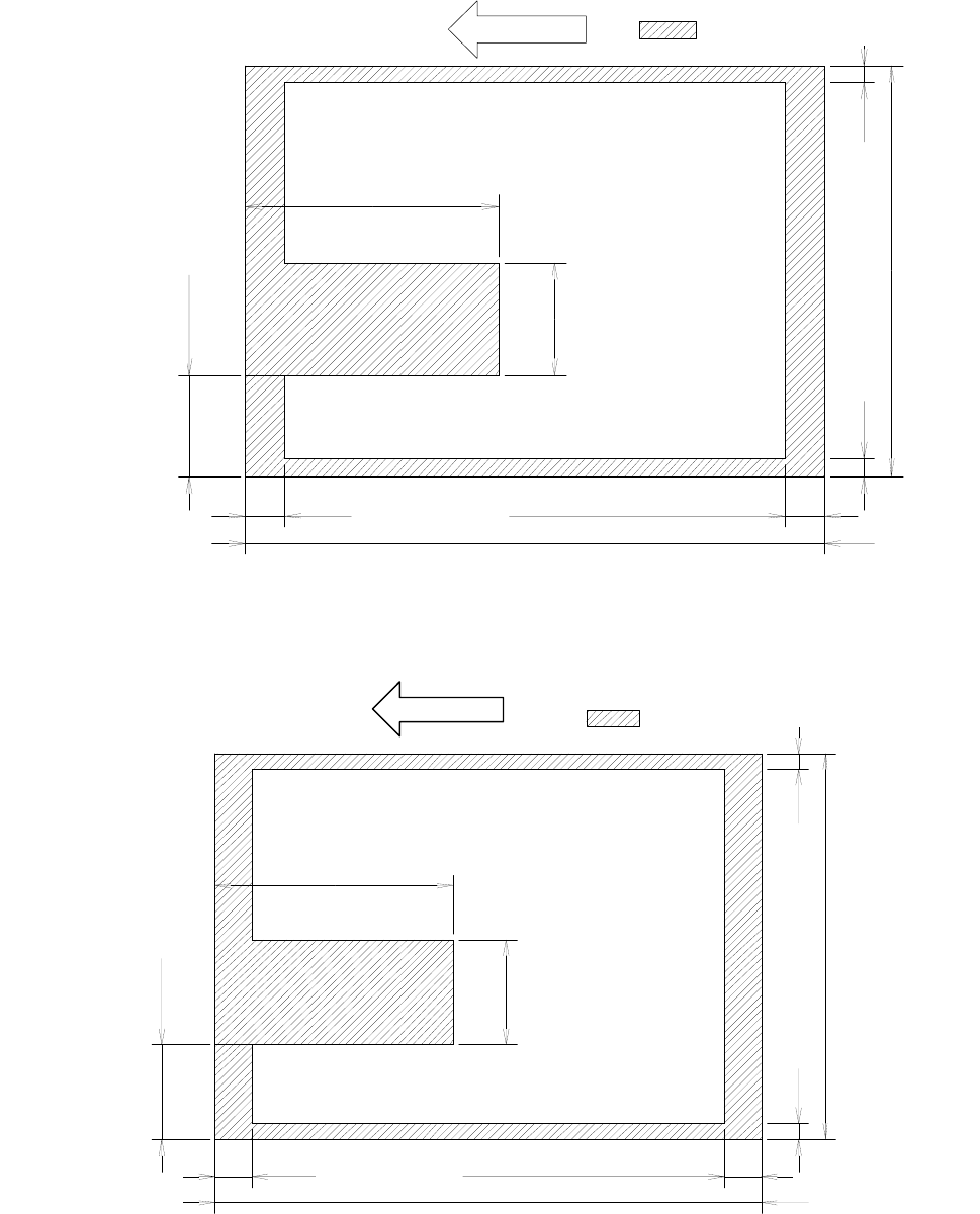
Figure 2 Bottom surface view of PWB
JX-100 LED
Figure 3 Bottom surface view of PWB – Board size in X direction : 410 mm or less
: Support pin setup disable
Position adjustment
range by board width
10 mm for a board size of 320 mm or more
0~200mm
50mm
95mm
Direction
はサポートピン設置不可範囲
5
0
~
3
6
0
m
m
50~410mm
5
0
m
m
95mm
40mm 基板サイズ370mm以上の時 40mm
4
m
m
4
m
m
0
~
9
5
m
m
基板幅による位置調整範囲
基板搬送方向
Direction
: Support pin setup disable
40 mm for a board size of 370 mm or more
Position adjustment
range by board width
11
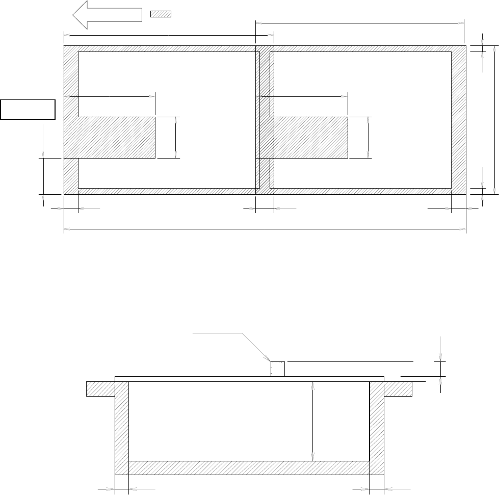
Figure 4 Bottom surface view of PWB – Board size in X direction : 410 mm or more
(3) Area where components can be placed on the PWB top side and bottom side.
部品
最
大
1
2
m
m
最
大
2
0
m
m
基板裏面 搭載可能範囲
3mm 3mm
Figure 5 Placement enable range in the height direction
4.6.5 PWBs clamping method
The PWB clamping method is based on the top surface of the board. The front/rear end
part of the board is pinched by the transport rail for both fixed side and moving side.
Marginal a rear side of the
board
Component
MAX.20mm
MAX.12mm
はサポートピン設置不可範囲
5
0
m
m
95mm
4
m
m
4
m
m
0
~
9
5
m
m
調
整範囲
基板搬送方向
5
0
~
3
6
0
m
m
40mm
410mm
~410mm
5
0
m
m
95mm
410mmより大きい~800mm
60mm 40mm
: Support pin setup disable
Adjustment
range
410 mm or more ~ 800
Direction
4.7 Function correcting the PWB positions
4.7.1 PWB positioning reference
• Shape reference only.
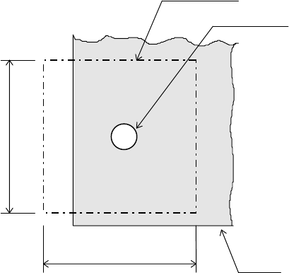
4.7.2 Field of vision for recognizing the PWB reference marks
□6.3 mm (camera’s field of vision for recognition).
Field of vision for PWBs recognition
Recognition mark
PWB
6.3mm
6.3mm
Figure 6 Field of vision for PWB recognition
4.7.3 Window size for recognizing the PWB reference marks
This size can be changed within a maximum of 6.3 mm, subject to securing a clearance
between the recognition mark and its surrounding area.
4.7.4 Kinds of recognition marks and corrective method
- PWB reference mark
Two or three marks (see Note 1and 2) are located on a PWB to correct the entire PWB.
When a machine detects two PWB reference marks, it corrects the positioning, angle
and expansion/contraction of the entire PWB. When detecting three PWB reference
marks, it corrects the perpendicularity in the X and Y direction also.
- Marks used to position the component area
Two marks (their positions can be set as you like) are to be provided to a group of
components placement positions, and they are used to correct each component
placement position in the group.
Note 1: The position is arbitrary, subject to not aligning three (3) reference makes,
if this is the case, on one (1) straight line. (It is recommended that the reference
marks should be made at the four (4) corners of the PWBs.
Note 2: If a board (more than 410 mm in X direction) is fed twice, two or three reference
marks (four or six in total) detected each time are required. (This is only for
JX-100 LED.)
12