JX-100_SPE_EN06.pdf - 第14页
10 (2) A range not available to set up the support pins JX-100 はサポ ー トピ ン 設置不可範囲 5 0 ~ 2 5 0 m m 50~ 330m m 3 2 m m 60mm 10mm 基板サイズ 3 2 0 mm以上の時 1 0 mm 4 m m 4 m m 8 ~ 1 0 5 m m 基板幅による 位置調整範囲 Figure 2 Bottom surface view…
9
4.6 Applicable PWBs
4.6.1 PWBs transport direction
Left to Right, Right to Left/ U-turn type conveyor
(The conveyor type can be switched between "Straight" and "U-turn".)
Rightward flow (carrying from left to right, looking from the front side)
Leftward flow (carrying from right to left, looking from the front side)
Note
:
Corresponding to a time of shipments from the factory.
4.6.2 PWB sizes and Mass
Machine type
Minimum size
(L
1
x W
1
)
(see Note 1)
Maximum size
(L
2
x W
2
)
(see Note 1)
Thickness T Weight (Mass)
JX-100 50×50mm 330×250mm 0.4 to 2.0mm 1,000 g or less
JX-100 LED 50×50mm
410 (see Note 2)
×360mm
0.4 to 2.0mm 2,000 g or less
Note 1: L represents the size in the board feed direction and L represents the right-angle
direction. W/L should be 2 or less.
Note 2: PWB size can be supported up to 800 mm by split clamping.
4.6.3 Allowable value of board warp
The allowable board warp is 0.2 mm or less per 50 mm, and 1 mm or less for both upper
warp and lower warp (conforming to JIS B 8461)
4.6.4 Limitations on PWBs
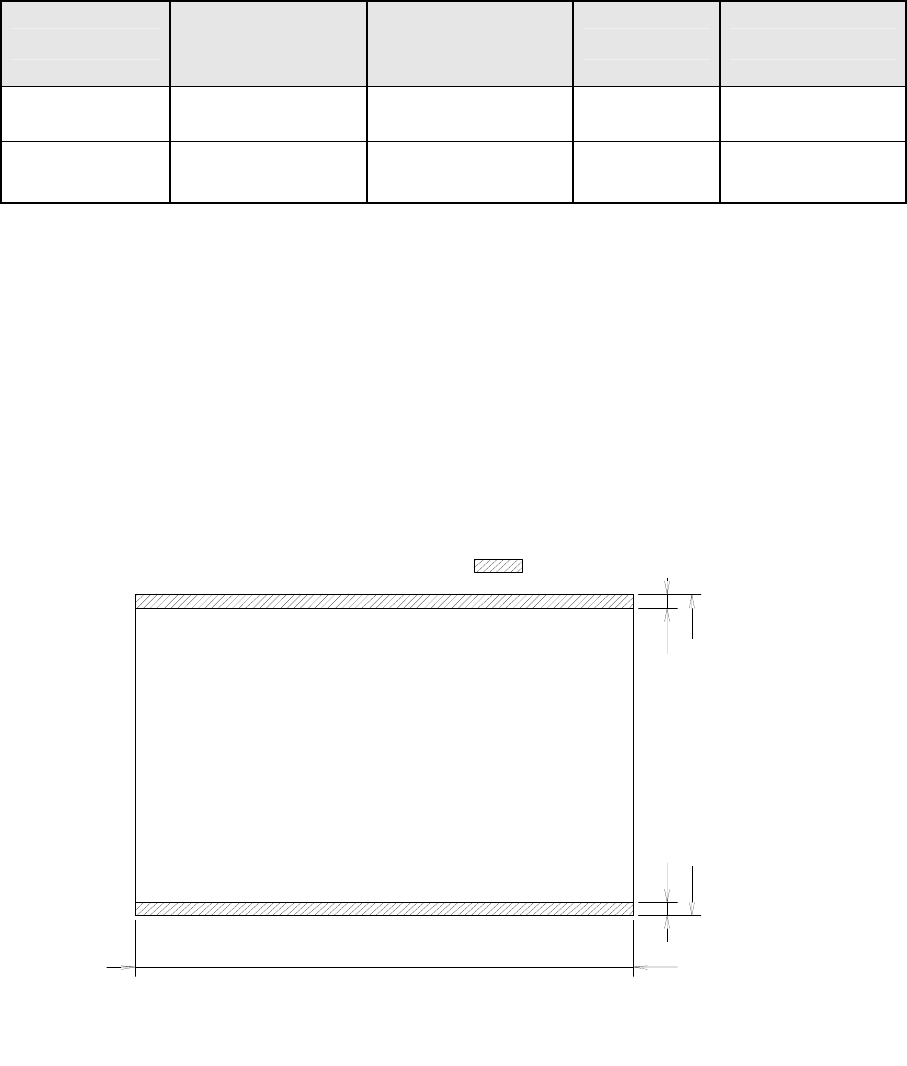
(1) A range not available to place the components)
Figure 1 Placement disable range of the top surface of PWB
は搭載不可範囲
3
m
m
3 mm
50~250mm
50~330mm
JX-100 50 to 330 mm
JX-100 LED 50 to 410 (800) mm
JX-100 LED 50 to 360 mm
JX-100 50 to 250 mm
Placement disables range
10
(2) A range not available to set up the support pins
JX-100
はサポートピン設置不可範囲
5
0
~
2
5
0
m
m
50~330mm
3
2
m
m
60mm
10mm 基板サイズ320mm以上の時 10mm
4
m
m
4
m
m
8
~
1
0
5
m
m
基板幅による位置調整範囲
Figure 2 Bottom surface view of PWB
JX-100 LED
Figure 3 Bottom surface view of PWB – Board size in X direction : 410 mm or less
: Support pin setup disable
Position adjustment
range by board width
10 mm for a board size of 320 mm or more
0~200mm
50mm
95mm
Direction
はサポートピン設置不可範囲
5
0
~
3
6
0
m
m
50~410mm
5
0
m
m
95mm
40mm 基板サイズ370mm以上の時 40mm
4
m
m
4
m
m
0
~
9
5
m
m
基板幅による位置調整範囲
基板搬送方向
Direction
: Support pin setup disable
40 mm for a board size of 370 mm or more
Position adjustment
range by board width
11
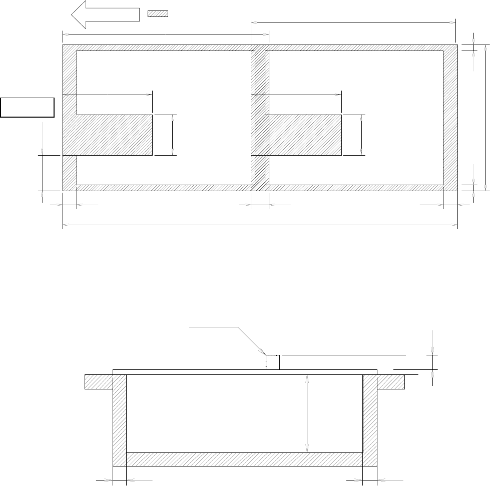
Figure 4 Bottom surface view of PWB – Board size in X direction : 410 mm or more
(3) Area where components can be placed on the PWB top side and bottom side.
部品
最
大
1
2
m
m
最
大
2
0
m
m
基板裏面 搭載可能範囲
3mm 3mm
Figure 5 Placement enable range in the height direction
4.6.5 PWBs clamping method
The PWB clamping method is based on the top surface of the board. The front/rear end
part of the board is pinched by the transport rail for both fixed side and moving side.
Marginal a rear side of the
board
Component
MAX.20mm
MAX.12mm
はサポートピン設置不可範囲
5
0
m
m
95mm
4
m
m
4
m
m
0
~
9
5
m
m
調
整範囲
基板搬送方向
5
0
~
3
6
0
m
m
40mm
410mm
~410mm
5
0
m
m
95mm
410mmより大きい~800mm
60mm 40mm
: Support pin setup disable
Adjustment
range
410 mm or more ~ 800
Direction