JX-100_SPE_EN06.pdf - 第7页
3. SYSTEM CONFIGURATION 3.1 JX-100 System Configuration z JX-100 Signal light with buzzer The device or function enclosed with dotted line is an op tion. *1: The option marked (*1) is delivered at const ruction work. *2:…

Low Component Lost Rate
① The pick position accuracy of the tape feeder and bank is stabilized to improve the pick
ratio.
② As process of component measurement operation performed while Component data is
being created, components are returned to the feeder from which they were picked up
after measurement.
Space saving
① As compared with the conventional model KE-2070, the model size is miniaturized
about 10% in the installation area ratio, so that space saving is attained.
Improvement of Versatility
① With the laser align sensor LNC60 head, laser recognition can be performed for
components of 0603(mm) or more with a size of up to □33.5 mm
② A bad mark indicating a defective circuit can be detected with an OCC.
③ Large size (410 x 360 mm) is available for JX-100 LED. Moreover, a board
whose dimensions are 410 to 800 mm in X direction is helpful to produce a
longer PWB whose dimensions are 800 x 360 mm when it is fed twice.(JX-100
LED only)
Improvement of Operability
① Touch panel is provided as standard. This can simplify key operations.
② With a USB port, a memory unit such as USB flash memory can be used.
③ Ethernet port allows you to transmit the data through a connection with LAN.
(Only JX-100 LED can be connected with LAN, but neither HLC nor IS can be done.)
High Serviceability
① A user level setting such as the operator, programmer, and administrator can be
performed.
② For the troubleshooting by operators, the HELP functions were fulfilled.
③ A nozzle filter can be replaced easily.
High Flexibility
① Component data can be created with the functions of “Export”, “Import” and
“Re-search” of the component database (Flexline DB).
② The production program created with FX series and KE series can be read.
③ A new laser ten plate widens the handling of odd-shaped components such as a dome
type LED, a side view type LED(JX-100 LED only), etc.
Corresponding to the safety standards
① The machine available with Europe CE marking. (EN machine only)
2
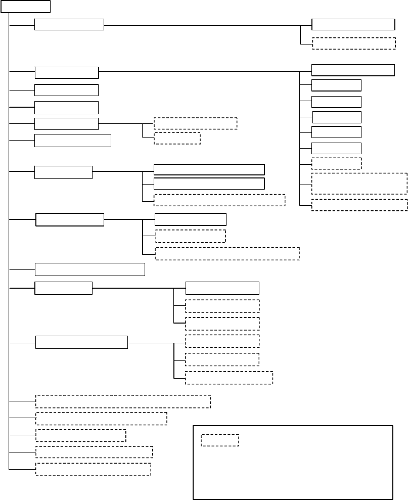
3. SYSTEM CONFIGURATION
3.1 JX-100 System Configuration
z
JX-100
Signal light with buzzer
The device or function enclosed with dotted
line is an option.
*1: The option marked (*1) is delivered at construction work.
*2: Type 1 or type 2 is available for the rear as an option.
*3: In the USA, China, and Singapore, the air compressor
must be procured locally because the export of this item
is prohibited.
Power supply unit
CPU board
I/O control unit
Cabinet
Liquid crystal display
Keyboard
Mouse
USB port
Touch panel
SSD
Emergency stop button
Leakage breaker (*1)
DVD/CD-ROM drive
(USB connection)
Motor control unit
External Programming Unit (EPU)
FDD (USB connection)
HOD
Head unit
Height Measurement System (HMS)
Offset correction camera (OCC)
Laser recognition head (LNC60)
Outline reference Placement station
Automatic Tool Changer (ATC)
Feeder bank Front fixing bank
Rear fixing band (*1)
Trash box
Pneumatic piping systems
Bulk feeder, Tape feeder, Stick feeder
Tray holder (*2)
Vacuum pump (*1)
Main line filter
X-Y positioning unit
Air compressor Assembly (*3)
Simple Buffer
Caster (*1)
Extension guide of the conveyor (100mm)
(*1)
Quick connect coupling
Feeder float detecting function, Front/Rear (*1)
3
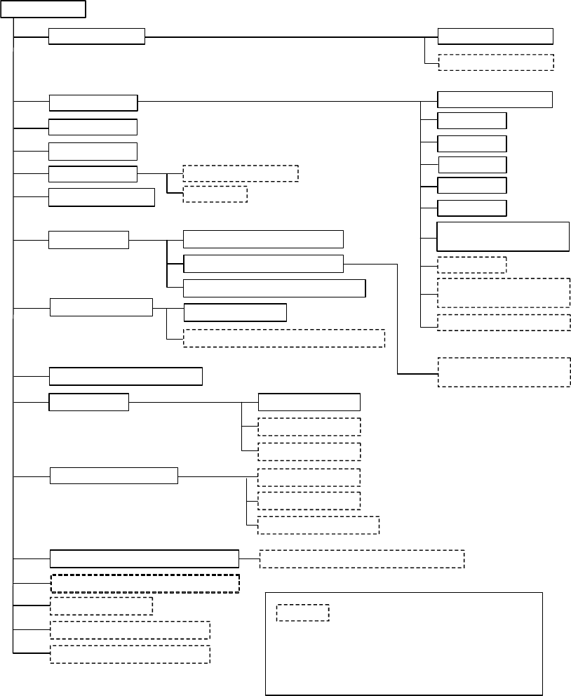
3.2 JX-100 LED System Configuration
z
JX-100 LED
Signal light with buzzer
The device or function enclosed with dotted
line is an option.
*1: The option marked (*1) is delivered at construction work.
*2: Type 1 or type 2 is available for the rear as an option.
*3: In the USA, China, and Singapore, the air compressor
must be procured locally because the export of this item
is prohibited.
Power supply unit
CPU board
I/O control unit
Cabinet
Liquid crystal display
Keyboard
Mouse
USB port
Touch panel
SSD
Caster (*1)
Emergency stop button
Leakage breaker (*1)
DVD/CD-ROM drive
(USB connection)
Motor control unit
FDD (USB connection)
HOD
Head unit
Laser recognition head (LNC60)
Outline reference
Placement station
Automatic Tool Changer (ATC)
Feeder bank Front fixing bank
X-Y positioning unit
100 BASE/10 BASE T
Ethernet port
Rear fixing bank (*1)
Trash box
Feeder float detecting function, Front
Pneumatic piping system
Tray holder (*2)
Vacuum pump (*1)
Main line filter
Air compressor Assembly (*3)
Extension guide of the conveyor (100mm)
(*1)
Offset correction camera (OCC)
Height Measurement System (HMS)
*1
(
)
Lighting unit of solder
recognition
Quick connect coupling
Feeder float detecting function, Rear(*1)
Bulk feeder, Tape feeder, Stick feeder
External Programming Unit(EPU)
4