JX-100_SPE_EN06.pdf - 第11页
4.2 Component placement Cycle Time (A Number of Components to Be Placed Per Hour) Laser recognition 15,300 CPH (conforming to IPC9850) *1: This is a number of components to be placed for one hour when 400 1608 capacitors…
6
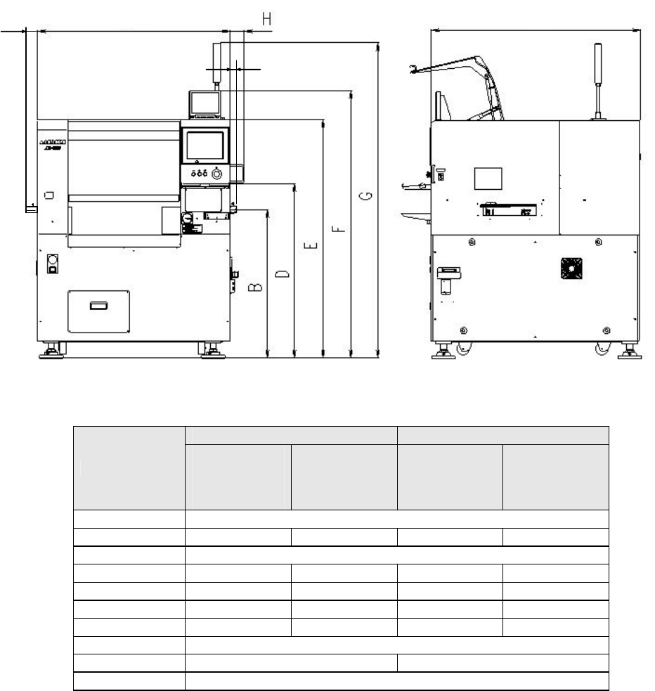
4.1.1 Machine dimensions
(mm)
JX-100 JX-100 LED
Dimensions
Board
transport
height
900mm
Board
transport
height
950mm
Board
transport
height
900mm
Board
transport
height
950mm
A 1170
B 900 950 900 950
C 1270
D 1060 1110 1060 1110
E 1440 1490 1440 1490
F 1620 1670 1620 1670
G 1910 1960 1910 1960
H 65
J 125(EN:130) 145(EN:150)
K 75(EN:80)
4.1.2 Mass
JX-100, JX-100 LED :1,000kg
J
K
C
A
4.2 Component placement Cycle Time (A Number of Components to Be
Placed Per Hour)
Laser recognition
15,300 CPH (conforming to IPC9850)
*1: This is a number of components to be placed for one hour when 400 1608 capacitors
are placed onto a 200 mm × 200 mm board at an angle of 0, 90, 180 and 270 degrees
sequentially.
*2: Simultaneous pickup and sequential placement of all the nozzles
*3
Conditions for placing the 0603 components: HMS (option for JX-100) is required. And the
system does not perform the simultaneous pickup but only the sequential pickup; the cycle
time is 10,300 CPH.
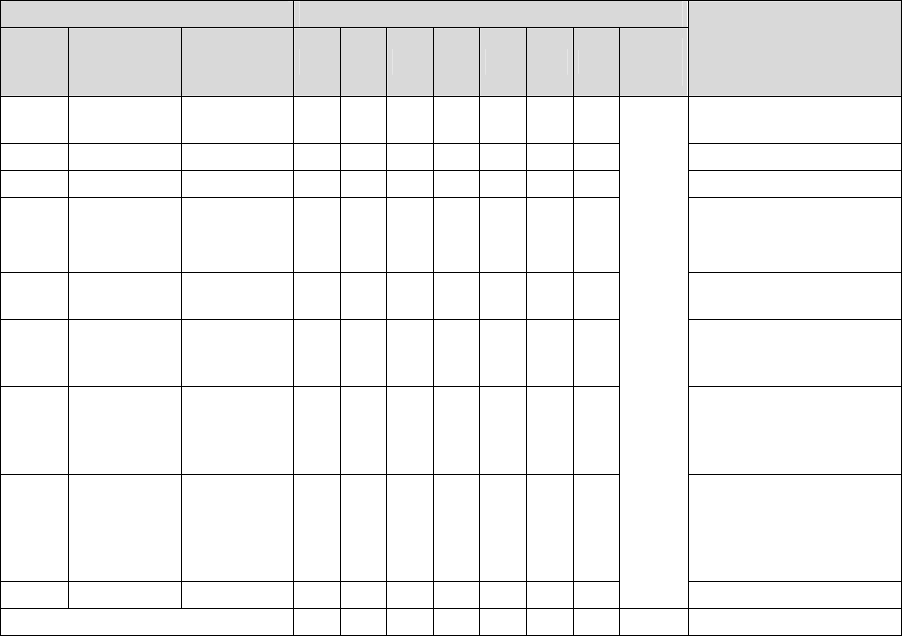
4.3 Nozzles
Various types of nozzles have been designed to increase the reliability of placement of
each type of components as shown in the table below.
For the standard attached nozzle, select from among the nozzles shown in the table below.
Table 1 Nozzles supplied as the standard devices
Nozzle Nozzle assembly
NO.
Internal
diameter of
a nozzle
External
diameter of
a nozzle
A B
E
F
G
H
J
Std.
nozzle
select
Applicable components
(reference)
500 2-φ0.4 1.0 x 0.5 - 6 - - - -
-
1005, 1608, 2012
* See Note 2
SOT (Molding: 1.6 x 0.8)
501 φ0.25 0.7 x 0.4 - - - - - -
-
0603 *See Note 3
502 φ0.4 φ0.7 6 - 3 - - 3
2
1005
503 φ0.6 φ1.0 6 - 6363
6
1608, 2012,
SOT (Molding: 1.6 x 0.8),
SOT (Molding: 2.0 x 1.25)
504 φ1.0 φ1.5 - 43663
4
2012, 3216, MELF, SOT23,
SOT (Molding: 2.0 x 1.25)
505 φ1.7 φ3.5 1 2 3 3 1 3
2
Aluminum electrolytic
capacitor (small), tantalum
electrolytic capacitor, trimmer
506 φ3.2 φ5.0 1 1 1 3 1 3
1
Aluminum electrolytic
capacitor (medium),
SOP (narrow type),
SOJ, Connector
507 φ5.0 φ8.5 1 1 - 111
1
Aluminum electrolytic
capacitor (large),
SOP (wide type),
TSOP, QFP, PLCC, SOJ,
Connector
508C φ8.0 φ9.5 1 1 1 1 1 1
1
*See
Note 1
QFP, PLCC, BGA
Total number of nozzles 16
15
17
17
16
17
17 16
* You can select a standard nozzle only.
* Total number of nozzles that can be installed onto an ATC station: 26. (There is not any
setting for a large type of nozzles.)
Note 1: For a Std. Nozzle Select, you can choose 15 nozzles from Nozzle No.500 to 508C.
However, a nozzle for machine calibration must be included in it.
One piece from among a No. 500, a No. 502 and a No. 503 nozzle to be
used for laser calibration
One piece of a No. 508C nozzle to be used for head offset
7
Note 2:Since a theta error may occur due to the shape of the surface of a 2012R
component to be picked (such as differences of manufactures and/or resistance
values), use a No. 504 nozzle if you have to place 2012R components in the high
density (the gap between the adjacent components: 0.3 mm or less).
Note 3 : To place a 0603 component on a board, a No. 501 nozzle, a dedicated tape
feeder and a HMS are required. (A HMS is supplied with JX-100LED without any
extra charge.)
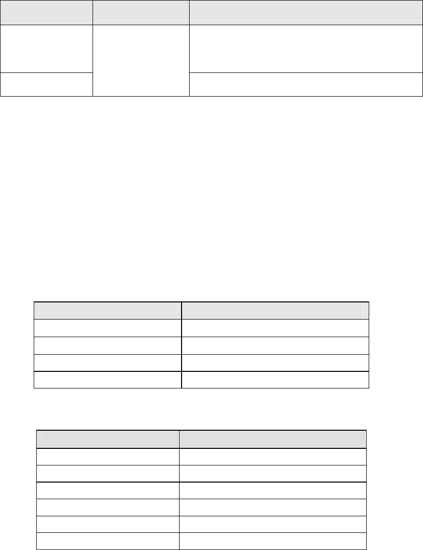
4.4 Applicable Component
4.4.1 Applicable component sizes
(1) Component size
Unit: mm
Recognition device Applicable component size
Length × Width
Minimum length: 0.6 × 0.3 (see Note 1)
Maximum length : 33.5
(see Note 2)
Square component : □ 33.5
(see Note 2)
Component height
LNC60 laser
recognition device
0.09 to 12.0 (see Note 3)
Note 1: HMS (option for JX-100) is required when the 0603 component is placed.
Moreover, it is sequentially picked up.
Note 2: The maximum size of components that can be recognized with 6 nozzles of the LNC60 at
the same time is □ 10.0 mm. When you are to place components whose size is more
than □ 10.0 mm with the LNC60 head, only three heads are used to pick them up.
Note 3: The minimum component height varies depending on component size. To be exact,
the component height depending on the window width is set, the smaller the diagonal
width of component, the smaller the value of the minimum component height. To
cite JX-100 LED, if the board dimension in X direction is 630 to 680 mm, the
maximum component height is 9.0 mm.
4.5 Component Placement Accuracy at X, Y and θ
* The placement accuracy is achieved when the PWB mark is used.
Placed positions (X, Y)
Unit: μm
Component type
Placement accuracy (±3σ)
Square chip(0603 or more)
± 50
Square chip LED (3216)
± 50
MELF
± 100
SOT
± 150
Placed posture (θ)
Unit: °
Component type
Angle
Square chip of 0603
± 3.0
Square chip of 1005
± 2.5
Square chip of 1608 or more
± 2.0
Square chip of 3216 LED
± 3.0
MELF
± 3.0
SOT
± 3.0
8