Infinity EX Camera System Module.pdf - 第11页
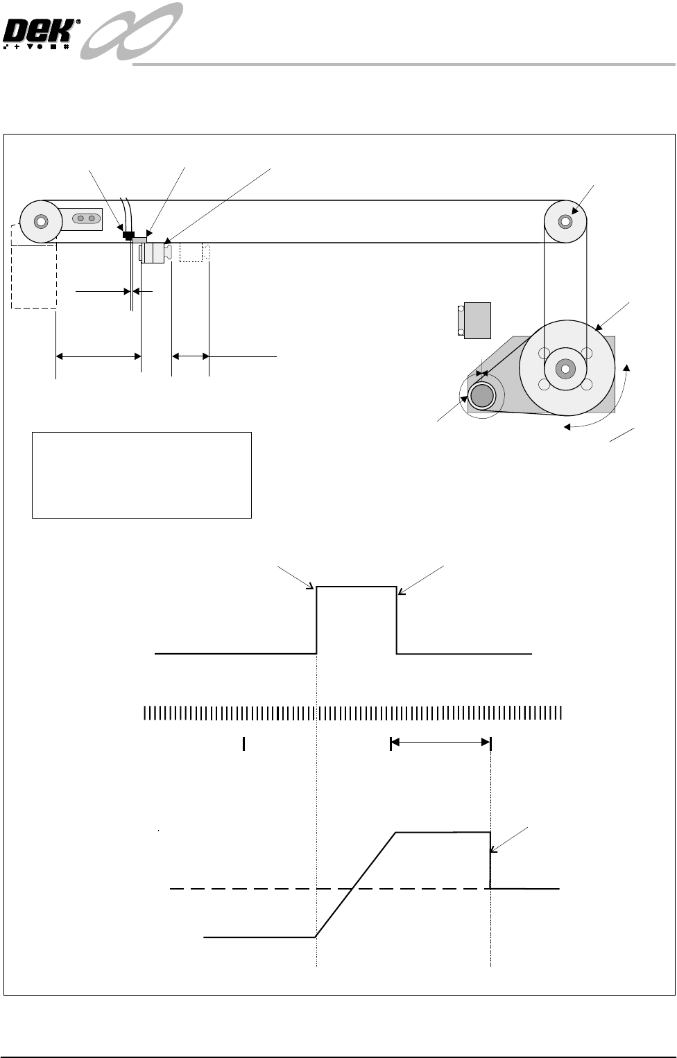
INFINITY EX CAME RA SYSTE M MODULE MECHANICAL DETAIL Chapter Issue 3 J an 04 Technical Reference Manual 17.11 Camera Y Axis Mechanism 1 Rev = 4000 Counts 1 Rev = 22T x 5mm = 110mm P ulley Ratio = 76T/22T = 1 : 3.45 110mm…
INFINITY
EX
CAMERA SYSTEM MODULE
MECHANICAL DETAIL
17.10 Technical Reference Manual Chapter Issue 3 Jan 04
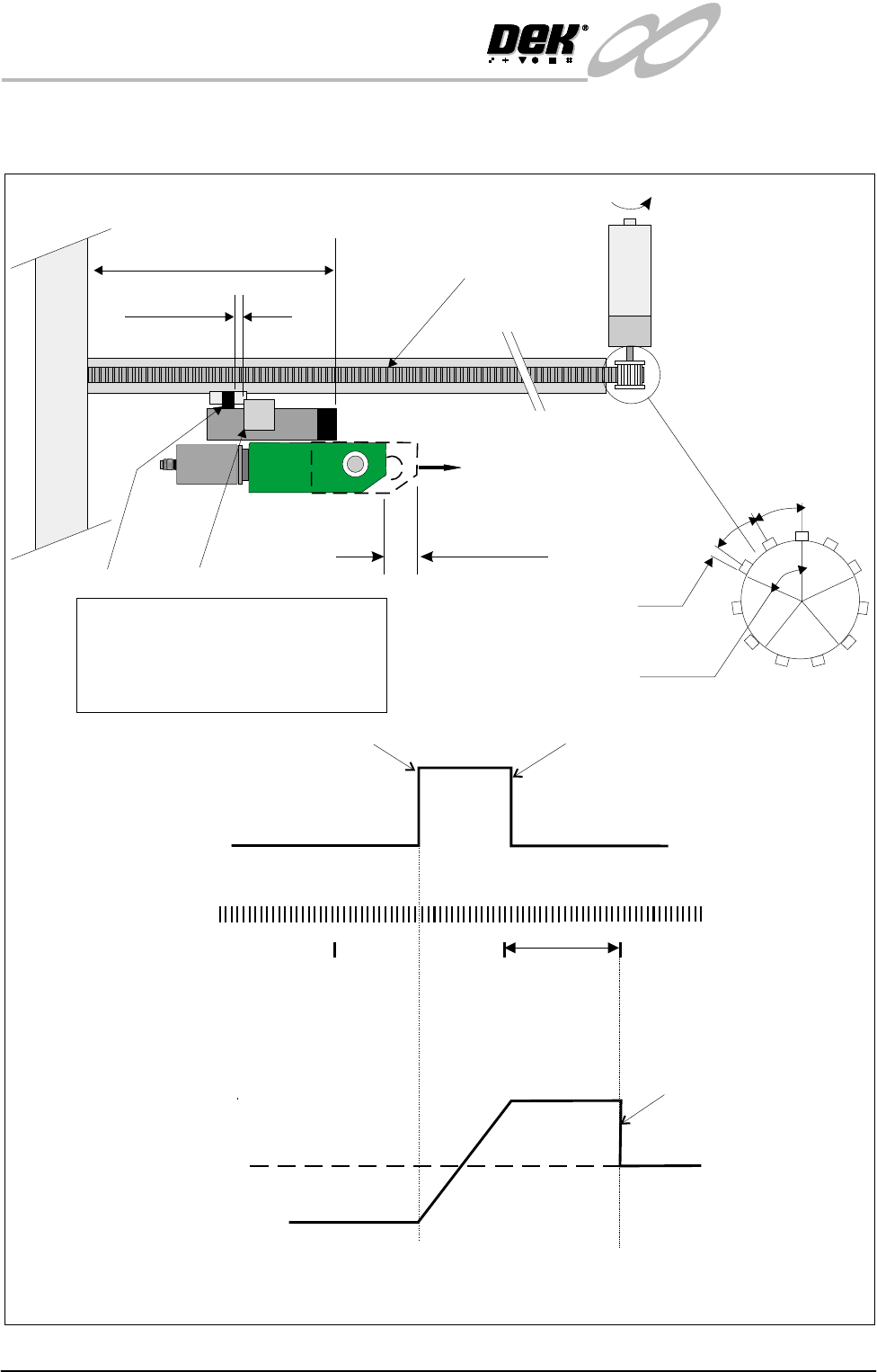
Camera X Axis Mechanism
Stop
Forward
1 Rev
(22mm)
Motor Stops
Home Position
NOTE
To home the motor in the X axis, the motor drives in the reverse direction until it sees
the home sensor. The motor changes direction to drive the vane out of the home sensor.
On receipt of the next encoder index pulse the motor stops.
Reverse
Servo
Motor
Vane Leaves Sensor
Vane Enters Sensor
Home
Sensor
0
+12
Position
Pulse
Encoder
Index Pulses
Pulley diameter = 11 x 10mm (pitch) = 110mm
1 Rev of Encoder = 4000 counts
1 Rev of Encoder = 1/5 pulley Rev
1/5 x 110mm = 22mm
1 Rev
11 AT
1/5 Rev
5 : 1 Gearbox
134 - 139mm
1-2mm
Timing Belt
22mm
Sensor
Vane
Index Pulse
Occurrence
22mm
2T = 20mm
2mm
PULNIX
TM-6EX
INFINITY
EX
CAMERA SYSTEM MODULE
MECHANICAL DETAIL
Chapter Issue 3 Jan 04 Technical Reference Manual 17.11
Camera Y Axis Mechanism
1 Rev = 4000 Counts
1 Rev = 22T x 5mm = 110mm
Pulley Ratio = 76T/22T = 1 : 3.45
110mm / 3.45 = 31.8mm
22AT
Vane Leaves Sensor
Vane Enters Sensor
+12
0
1 Rev
Motor Stops
Home Position
Forward
Stop
Reverse
Servo
Motor
(31.8mm)
Home
Sensor
Position
Pulse
Encoder
Index Pulses
31.8mm
28 - 30mm
1 -2mm
Home
Position
76AT
11AT x 10mm
Camera Carriage
Home Sensor
Vane
3.45
Turn1
INFINITY
EX
CAMERA SYSTEM MODULE
DRIVES AND SENSORS
17.12 Technical Reference Manual Chapter Issue 3 Jan 04
DRIVES AND SENSORS
Sensors
Motors
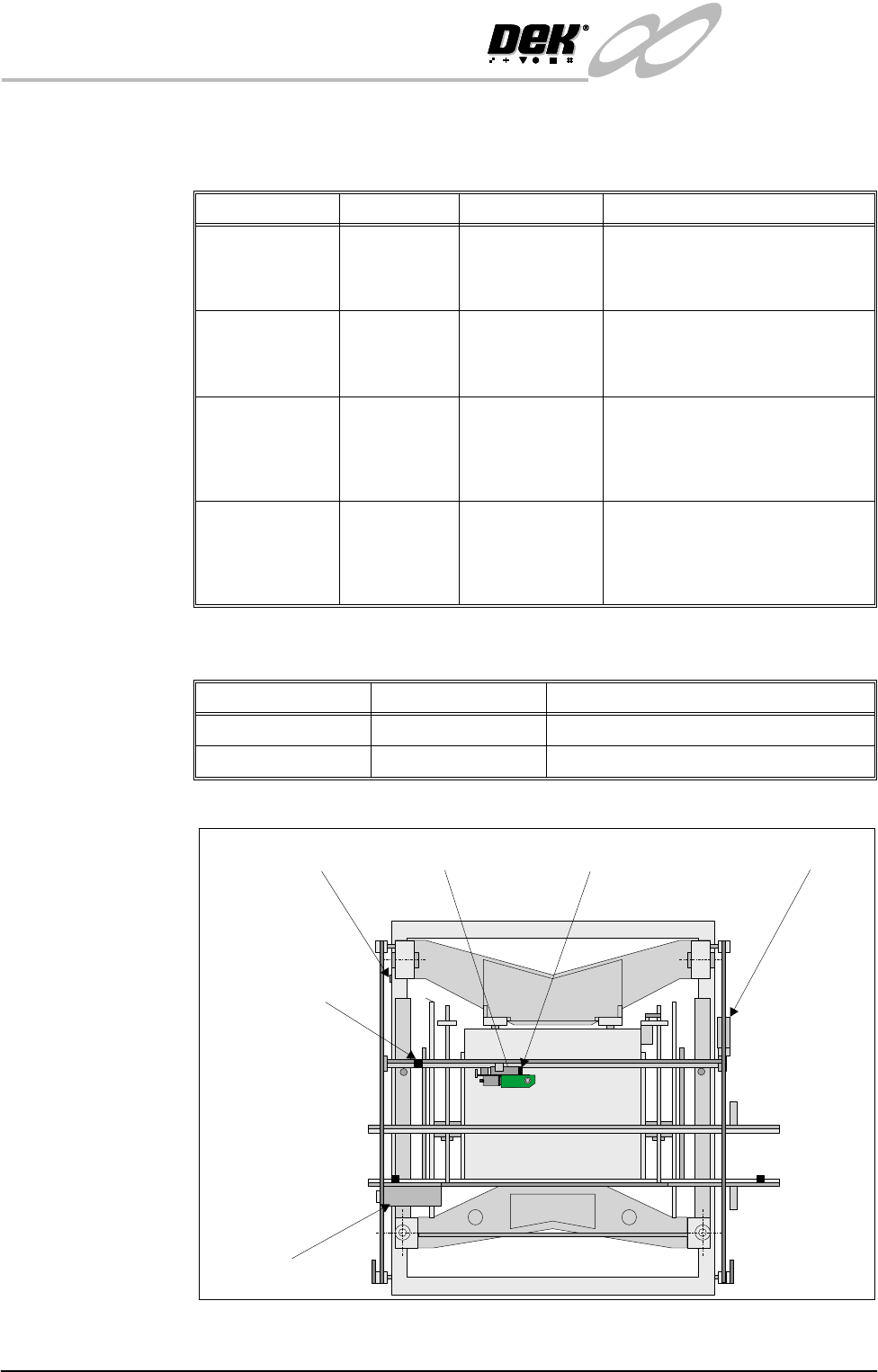
Figure 17-7 Drives and Sensors Location
Name Type Test Point Functional Description
Camera X Home
Sensor
Hall Effect NextMove X2
Dig IN 5
Used in conjunction with the respec-
tive encoder index pulses to provide
accurate repeatable home position-
ing in the camera X axis.
Camera Y Home
Sensor
Hall Effect NextMove X2
Dig IN 15
Used in conjunction with the respec-
tive encoder index pulses to provide
accurate repeatable home position-
ing in the camera Y axis.
Board Stop In Through
Beam Opto
NextMove X2
Dig IN 23
Detects when the board stop is low-
ered and is used to prevent a colli-
sion with the rails should the return
spring fail whilst the camera is trav-
eling over them.
Board at Stop Diffuse
Background
Suppressed
Opto
NextMove X2
Dig IN 22
Detects a board present at the board
stop during board load. Its sensitiv-
ity must be set such that it does not
detect tooling underneath it with the
rising table at board load height.
Name Type Functional Description
Camera X Servo Motor Moves the camera in the X direction
Camera Y Servo Motor Moves the camera in the Y direction
Camera CarriageYHome
Hall Effect Switch
BoardatStop
ReflectiveOpto
Camera Carriage X Home
Hall Effect Switch
BoardStopLowered
ThroughBeam Opto
Camera X Axis
DriveMotor
CameraY Axis
DriveMotor
PULNIX
TM-6EX
PULNIX
TM-6EX