Infinity EX Camera System Module.pdf - 第9页
INFINITY EX CAME RA SYSTE M MODULE MECHANICAL DETAIL Chapter Issue 3 J an 04 Technical Reference Manual 17.9 Figure 17-6 Gold Camera Optical and Lighting Unit Each lighting group can be se t by the operator to a lev el b…
INFINITY
EX
CAMERA SYSTEM MODULE
MECHANICAL DETAIL
17.8 Technical Reference Manual Chapter Issue 3 Jan 04
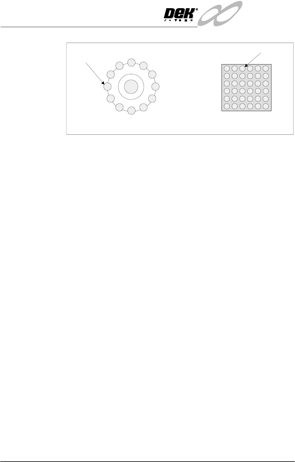
Figure 17-5 LED Ring Lighting
Each lighting group can be set by the operator to a level between 0 and 15, where
15 is the brightest.
The set levels for the lighting are stored in the product file, allowing a lighting
setup to be transferred from one machine to another simply by loading a new
product file.
Gold Camera The gold camera consists of two CCD cameras viewing through an optical unit
at either the board or screen. Images are simutaneously captured, processed by
individual vision cards and displayed in separate vision windows on the MMI.
The image quality is maintained by the use of high resolution (752 x 582 pixels)
cameras. The field of view of each camera is 11.5 x 8.5 mm giving the operator
a large active region of interest.
Optical and Lighting
Unit
The optical and lighting unit performs three main functions:
• Redirection of the board and screen images onto the camera sensor
• Illumination of the board and screen for image capture
• Focusing of the board and screen images
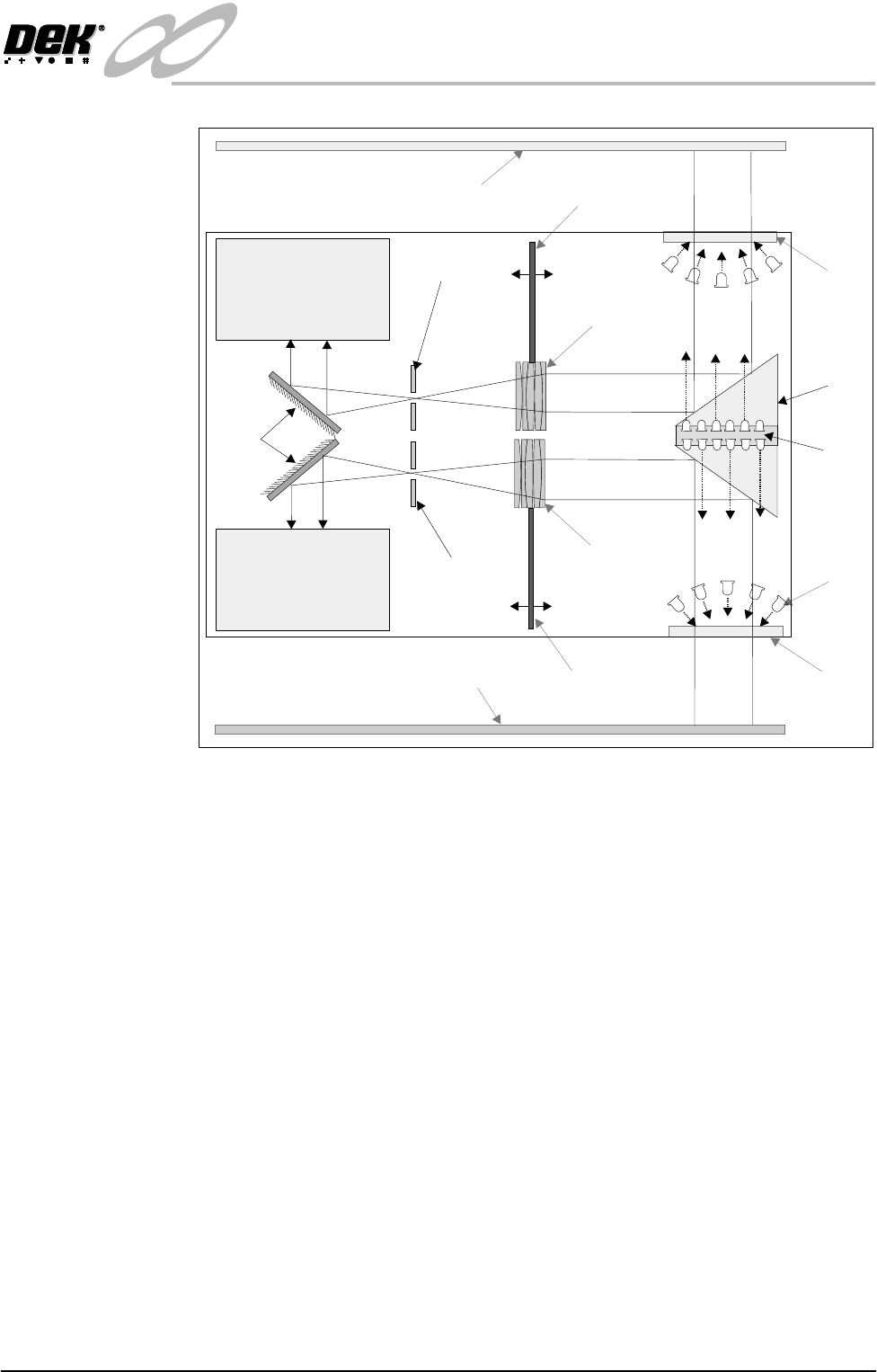
The board and screen images pass through their respective glass window to the
prism, which deflects the images by 90° towards the lens block. The images
pass through the lens blocks, which deflect the beams through the telecentric
stops. A set of mirrors deflect the images 90° to the their respective camera.
The distance between the lens block and the telecentric stop is fixed. By moving
the lens block and telecentric stop in relation to the optical unit enables focusing
to take place.
The camera focus is factory set and cannot be adjusted by the user.
The optical unit employs LEDs for direct and oblique lighting. The direct
lighting is achieved by a block of 30 surface mounted LEDs, one block for board
lighting and one for screen lighting. The oblique lighting is achieved by a ring
of twelve LEDs around the glass window, one ring for board lighting and one
for screen lighting.
Direct Lighting LED
Oblique Lighting LED
Plan View of Screen Oblique Lighting
(board oblique lighting is a mirror image)
Plan View of Screen Direct Lighting
(board direct lighting is a mirror image)
INFINITY
EX
CAMERA SYSTEM MODULE
MECHANICAL DETAIL
Chapter Issue 3 Jan 04 Technical Reference Manual 17.9
Figure 17-6 Gold Camera Optical and Lighting Unit
Each lighting group can be set by the operator to a level between 0 and 15, where
15 is the brightest.
The set levels for the lighting are stored in the product file, allowing a lighting
setup to be transferred from one machine to another simply by loading a new
product file.
Prism
Lens Block
Lens Block
Telecentric
Stop
Telecentric
Stop
Mirror
Direct
Lighting
Screen
Board
Glass
Window
Glass
Window
Oblique
Lighting
Focus
Focus
Camera 1
Camera 2
INFINITY
EX
CAMERA SYSTEM MODULE
MECHANICAL DETAIL
17.10 Technical Reference Manual Chapter Issue 3 Jan 04
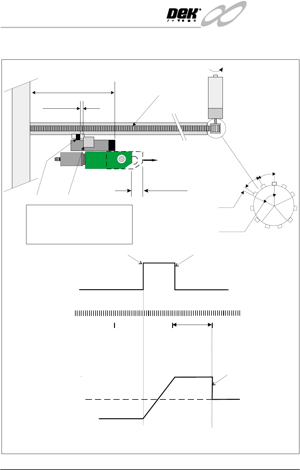
Camera X Axis Mechanism
Stop
Forward
1 Rev
(22mm)
Motor Stops
Home Position
NOTE
To home the motor in the X axis, the motor drives in the reverse direction until it sees
the home sensor. The motor changes direction to drive the vane out of the home sensor.
On receipt of the next encoder index pulse the motor stops.
Reverse
Servo
Motor
Vane Leaves Sensor
Vane Enters Sensor
Home
Sensor
0
+12
Position
Pulse
Encoder
Index Pulses
Pulley diameter = 11 x 10mm (pitch) = 110mm
1 Rev of Encoder = 4000 counts
1 Rev of Encoder = 1/5 pulley Rev
1/5 x 110mm = 22mm
1 Rev
11 AT
1/5 Rev
5 : 1 Gearbox
134 - 139mm
1-2mm
Timing Belt
22mm
Sensor
Vane
Index Pulse
Occurrence
22mm
2T = 20mm
2mm
PULNIX
TM-6EX