Infinity EX Camera System Module.pdf - 第5页
INFINITY EX CAME RA SYSTE M MODULE MECHANICAL DETAIL Chapter Issue 3 J an 04 Technical Reference Manual 17.5 MECHANICAL DET AIL Gr een Camera The camera, through the optical unit, looks up and do wn simultaneously , this…
INFINITY
EX
CAMERA SYSTEM MODULE
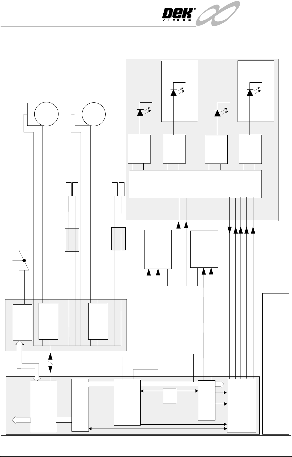
ELECTRICAL SCHEMATIC
17.4 Technical Reference Manual Chapter Issue 3 Jan 04
Gold Camera
Video
+12V
Camera 1
Video
Screen Direct
LEDs
24V
Constant
Current
Generator
Board Direct
LEDs
24V
Constant
Current
Generator
Constant
Current
Generator
Constant
Current
Generator
Screen Oblique LEDs
24V
Upper Lighting Board
Board Oblique LEDs
24V
Lower Lighting Board
Processor
NOTE
The CAN Bus forms part of the 100 way connection
between the Machine PC and Controller enclosures
R
S
2
3
2
NextMove
ISA 10
Processor
ISA 3
B
u
s
I
S
A
+12V
+12V
PSU
Strobe
Trig
Trig
Machine PC
SOURCE 4
Board Stop
Manual Operation
MultiMove1
X13
Y Camera Motor
Encoder
Servo
Motor
Encoder
Servo
Motor
X Camera Motor
+
_
+
_
Breakout
Board A
X Home Sensor
Y Home Sensor
DIG IN 15
DIG IN 5
Servo Drive
X8
Servo Drive
X10
Board Stop In (Up)
Board At Stop
DIG IN 23
DIG IN 22
Breakout
Board B
Machine Controller
CAN Bus
+24V(US)
Video
+12V
Camera 2
(Gold Camera
Option)
Video
Optical Unit
100 Way
P
C
I
B
u
s
Strobe
RX
0V
TX
24V U/S
Vision PC
Adaptor
ISA 5
Vision Card
PCI 3
Vision Card
PCI 2
(Gold Camera
Option)
INFINITY
EX
CAMERA SYSTEM MODULE
MECHANICAL DETAIL
Chapter Issue 3 Jan 04 Technical Reference Manual 17.5
MECHANICAL DETAIL
Green Camera The camera, through the optical unit, looks up and down simultaneously, this
allows the board image and stencil image to be displayed together on the monitor
screen.
To enable both images to be seen simultaneously, without degradation in picture
quality, a high resolution camera is used. The camera has a resolution of 752 x
582 pixels
Optical and Lighting
Unit
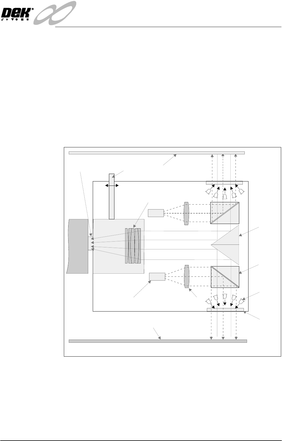
The optical and lighting unit performs three main functions:
• Redirection of the board and screen images onto the camera sensor
• Illumination of the board and screen for image capture
• Focusing of the board and screen images
Figure 17-2 Optical and Lighting Unit
Screen
Board
Optical Unit
Prism
Convex Lens
Glass
Window
Beam
Splitter
Cube
Oblique
Lighting
Lens Block
Telecentric Stop
Direct Lighting LED’s
Focus
Camera
Focus Assembly
INFINITY
EX
CAMERA SYSTEM MODULE
MECHANICAL DETAIL
17.6 Technical Reference Manual Chapter Issue 3 Jan 04
The board and screen images pass through their respective beam splitter cube to
the prism, which deflects the images by 90° towards the camera. The images
pass through a lens block which deflect the beams through the telecentric stop
to the camera. The distance between the lens block and the telecentric stop is
fixed. By moving the lens block and telecentric stop in relation to the optical
unit enables focusing to take place.
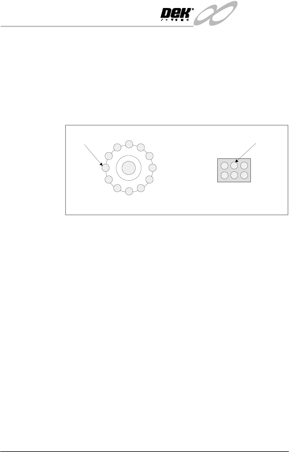
The optical unit employs LEDs for direct and oblique lighting. The direct
lighting is achieved by a block of six LEDs, one block for board lighting and one
for screen lighting. The oblique lighting is achieved by a ring of twelve LEDs
around the glass window, one ring for board lighting and one for screen lighting.
Figure 17-3 LED Ring Lighting
Each lighting group can be set by the operator to a level between 0 and 15, where
15 is the brightest.
The set levels for the lighting are stored in the product file, allowing a lighting
setup to be transferred from one machine to another simply by loading a new
product file.
Green Camera 2 The camera, through the optical unit, looks up and down simultaneously, this
allows the board image and stencil image to be displayed together on the monitor
screen.
To enable both images to be seen simultaneously, without degradation in picture
quality, a high resolution camera is used. The camera has a resolution of 752 x
582 pixels
Optical and Lighting
Unit
The optical and lighting unit performs three main functions:
• Redirection of the board and screen images onto the camera sensor
• Illumination of the board and screen for image capture
• Focusing of the board and screen images
Direct Lighting LED
Oblique Lighting LED
Plan View of Screen Oblique Lighting
(board oblique lighting is a mirror image)
Plan View of Screen Direct Lighting
(board direct lighting is a mirror image)