Infinity EX Camera System Module.pdf - 第42页
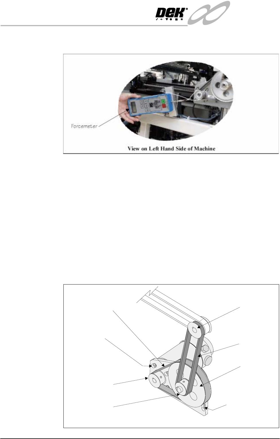
INFINITY EX CAME RA SY STEM MO DULE REP LAC EMEN T PR OCE DURE S 17.4 2 Technical Reference Manual Chapter Issue 3 Jan 04 8. Using a suitable cable tie, engage a forcemeter with the motor dri ve pulle y . Apply a force o…
INFINITY
EX
CAMERA SYSTEM MODULE
REPLACEMENT PROCEDURES
Chapter Issue 3 Jan 04 Technical Reference Manual 17.41
Camera Y Motor Timing Belt
1. Ensure the machine is powered down.
2. Remove the left hand machine side panel.
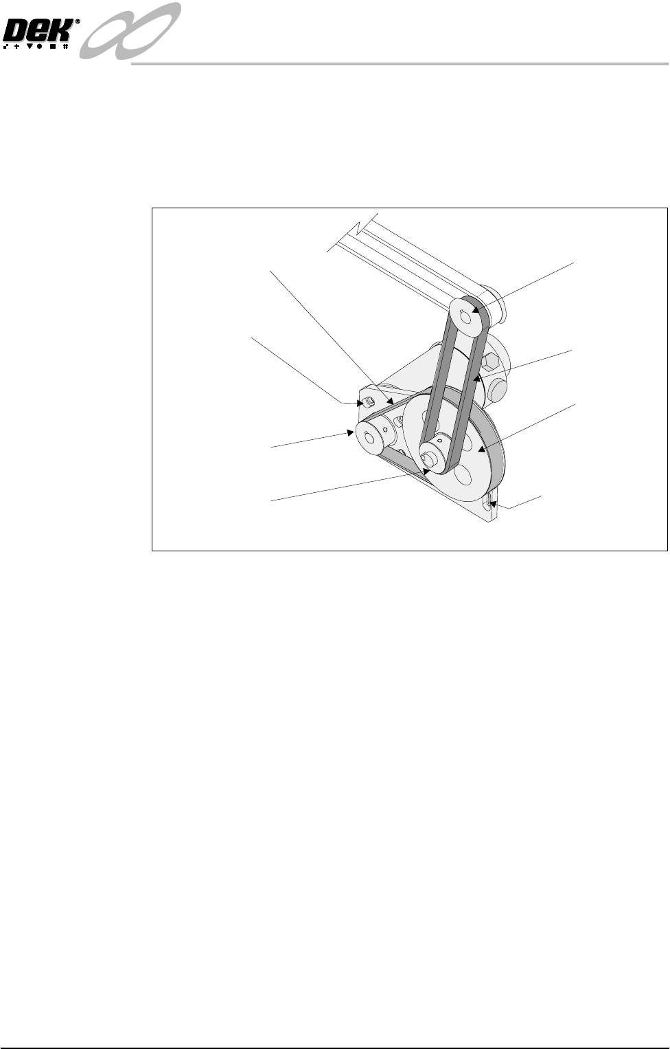
3. Loosen the four camera Y motor securing screws, slide the motor towards
the base casting releasing tension on the motor timing belt.
4. Loosen the four motor mounting plate securing screws, slide the mounting
plate towards the top of the machine releasing the tension on the motor
timing belt. Unship the belt from the Y drive shaft pulley.
5. Remove the motor timing belt and discard.
NOTE
Ensure the replacement motor timing belt is identical to the discarded belt.
6. Route the replacement timing belt around the Y motor drive and Y gear
pulleys.
7. Refit the motor transfer timing belt around the Y drive shaft pulley. Tension
the belt (Left Hand Y Transfer Timing Belt Replacement Procedure refers).
Camera Y Motor
Securing Screws
(In 4 Positions)
Motor Mounting Plate
Securing Screws
(In 4 Positions)
View on Left Hand Camera Y Axis Belt
Y Transfer
Timing Belt
Timing Pulley
Y Gear Pulley
Y Motor Timing Belt
Y Motor Drive Pulley
Y Drive Shaft Pulley
INFINITY
EX
CAMERA SYSTEM MODULE
REPLACEMENT PROCEDURES
17.42 Technical Reference Manual Chapter Issue 3 Jan 04
8. Using a suitable cable tie, engage a forcemeter with the motor drive pulley.
Apply a force of 10kg in the same plane as the motor securing screws.
9. Maintaining this force, tighten the four motor securing screws.
10.Replace the left hand machine side panel.
11.Power up and initialize the machine. Carry out the following checks:
a. Camera X Home Positioning.
b. Camera Y Home Positioning.
Left Hand Y Transfer Timing Belt
1. Ensure the machine is powered down.
2. Remove the left hand machine side panel.
3. Loosen the four motor mounting plate securing screws, slide the mounting
plate towards the top of the machine releasing tension on the transfer timing
belt.
Camera Y Motor
Securing Screws
(In 4 Positions)
Motor Mounting Plate
Securing Screws
(In 4 Positions)
View on Left Hand Camera Y Axis Belt
Y Transfer
Timing Belt
Timing Pulley
Y Gear Pulley
Y Motor Timing Belt
Y Motor Drive Pulley
Y Drive Shaft Pulley
INFINITY
EX
CAMERA SYSTEM MODULE
REPLACEMENT PROCEDURES
Chapter Issue 3 Jan 04 Technical Reference Manual 17.43
4. Remove the Y transfer timing belt and discard.
NOTE
Ensure the replacement transfer timing belt is identical to the discarded belt.
5. Route the replacement belt around the timing pulley and the drive shaft
pulley.
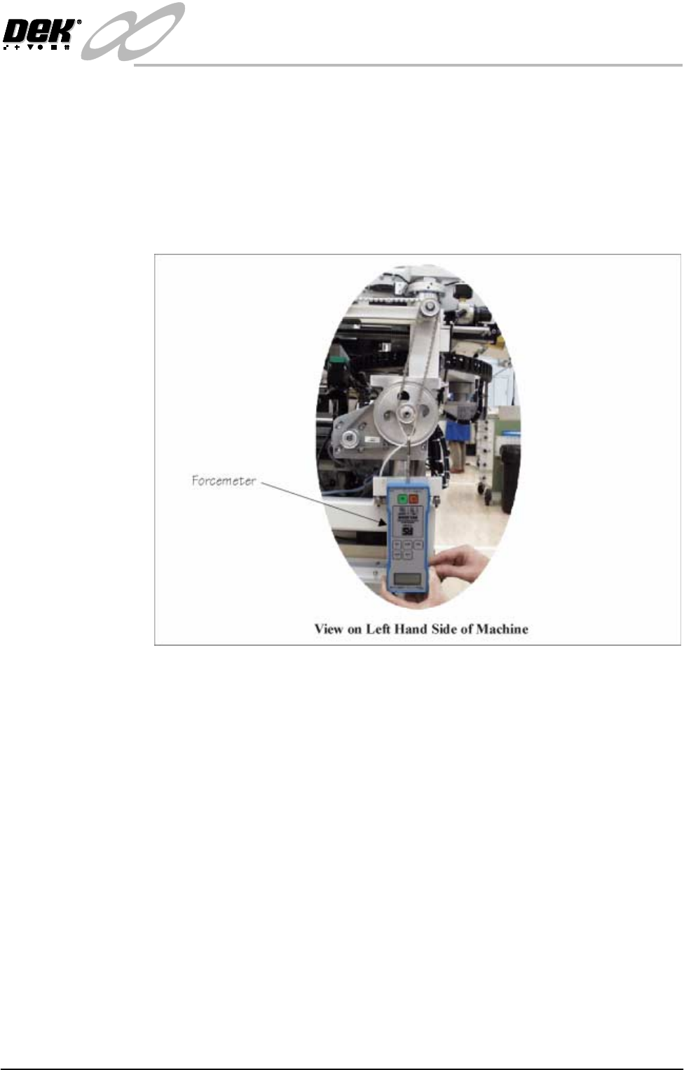
6. Using a suitable cable tie, engage a forcemeter with the drive shaft pulley.
Apply a vertical downward force of 11kg.
7. Maintaining this force, tighten the four motor mounting plate securing
screws.
8. Replace the left hand machine side panel.
9. Power up and initialize the machine. Carry out the following checks:
a. Camera X Home Positioning.
b. Camera Y Home Positioning.
Remote Board Stop to Camera Board Stop
Preparation Carry out Removing the Remote Board Stop, Rising Table Module Chapter,
Replacement Procedures refers.
External Services 1. With the machine switched off and the pneumatic supply disconnected,
remove the machine rear cover.
2. Remove the machine left hand side cover.