Infinity EX Camera System Module.pdf - 第18页
INFINITY EX CAME RA SY STEM MO DULE SEQUEN CES 17.1 8 Technical Reference Manual Chapter Issue 3 Jan 04 PULNIX TM-6EX PULNIX TM-6EX PULNIX TM-6EX WARNING-SHARP EDGE PA TENT No.5157438 WARNING-SHARP EDGE PA TENT No.515743…
INFINITY
EX
CAMERA SYSTEM MODULE
SEQUENCES
Chapter Issue 3 Jan 04 Technical Reference Manual 17.17
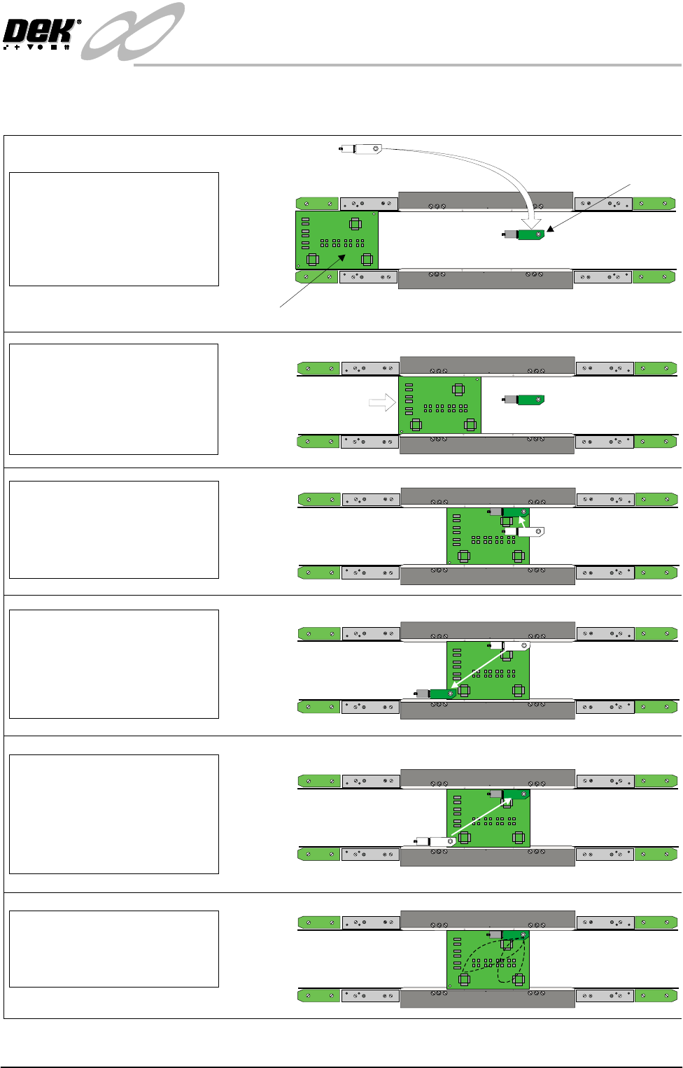
Camera Sequence - Full Inspection and SPC Enabled
PULNIX
TM-6EX
PULNIX
TM-6EX
PULNIX
TM-6EX
PULNIX
TM-6EX
WARNING-SHARP EDGE
PATENT No.5157438
WARNING-SHARP EDGE
PATENT No.5157438
Plan View on Rails (Printhead Removed)
Board
Camera
PULNIX
TM-6EX
WARNING-SHARP EDGE
PATENT No.5157438
WARNING-SHARP EDGE
PATENT No.5157438
WARNING-SHARP EDGE
PATENT No.5157438
WARNING-SHARP EDGE
PATENT No.5157438
WARNING-SHARP EDGE
PATENT No.5157438
WARNING-SHARP EDGE
PATENT No.5157438
PULNIX
TM-6EX
PULNIX
TM-6EX
WARNING-SHARP EDGE
PATENT No.5157438
WARNING-SHARP EDGE
PATENT No.5157438
PULNIX
TM-6EX
PULNIX
TM-6EX
WARNING-SHARP EDGE
PATENT No.5157438
WARNING-SHARP EDGE
PATENT No.5157438
PULNIX
TM-6EX
Step 1
Machine is initialized. Run is
pressed on MMI, the camera
is driven to the board stop
coordinates. The board stop
is lowered.
Step 3
The camera is driven to
Fiducial 1 coordinates.
Fiducial capture sequence
is completed.
Step 4
Camera is driven to Fiducial
2 coordinates. Fiducial
capture sequence is
completed. Screen
alignment is carried out.
Step 6
The camera is driven to the
inspection sites. Site
capture is completed.
Step 5
The camera recaptures
Fiducial 2, the camera is
driven to Fiducial 1
coordinates. Fiducial
recapture is completed.
Step 2
The board is transported
into the machine stopping
at the board stop and the
board clamps are activated.
The board stop is retracted.
INFINITY
EX
CAMERA SYSTEM MODULE
SEQUENCES
17.18 Technical Reference Manual Chapter Issue 3 Jan 04
PULNIX
TM-6EX
PULNIX
TM-6EX
PULNIX
TM-6EX
WARNING-SHARP EDGE
PATENT No.5157438
WARNING-SHARP EDGE
PATENT No.5157438
WARNING-SHARP EDGE
PATENT No.5157438
PULNIX
TM-6EX
PULNIX
TM-6EX
WARNING-SHARP EDGE
PATENT No.5157438
WARNING-SHARP EDGE
PATENT No.5157438
WARNING-SHARP EDGE
PATENT No.5157438
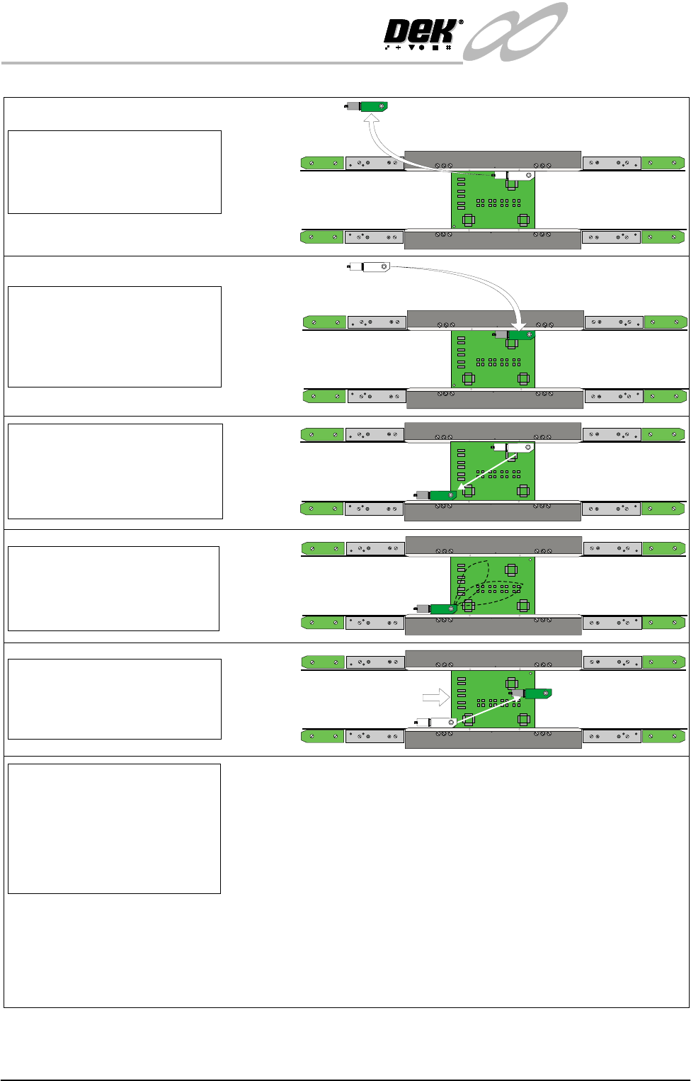
Step 8
The camera is driven to
Fiducial 1 coordinates.
Fiducial recapture sequence
completed.
Step 9
The camera is driven to
Fiducial 2 coordinates.
Fiducial recapture is
completed.
Step 10
The camera is driven to the
inspection sites. Inspection
site recapture is completed.
Step 11
Camera is driven to the
board stop coordinates. The
board exits the machine.
PULNIX
TM-6EX
PULNIX
TM-6EX
WARNING-SHARP EDGE
PATENT No.5157438
WARNING-SHARP EDGE
PATENT No.5157438
Step 12
Steps 2 -10 are repeated for
subsequent boards with
Pre-image set to Every.
Steps2-5and7-11are
repeated for subsequent
boards with Pre-image set to 1.
PULNIX
TM-6EX
PULNIX
TM-6EX
WARNING-SHARP EDGE
PATENT No.5157438
WARNING-SHARP EDGE
PATENT No.5157438
Step 7
The camera is driven to the
home position. The print
sequence is carried out.
NOTE
Machines with Pre-Print SPC enabled only, Steps 8-9 are omitted.
Machines with Post-Print SPC enabled only, Step 5 is omitted.
With selective print/pass through enabled, after Step 2 the camera is driven to the select mark coordinates. If the
select mark is recognized the sequence continues with Step 3. If the select mark is not recognized, the board is not
printed and exits the machine.
INFINITY
EX
CAMERA SYSTEM MODULE
POSITIONING
Chapter Issue 3 Jan 04 Technical Reference Manual 17.19
POSITIONING
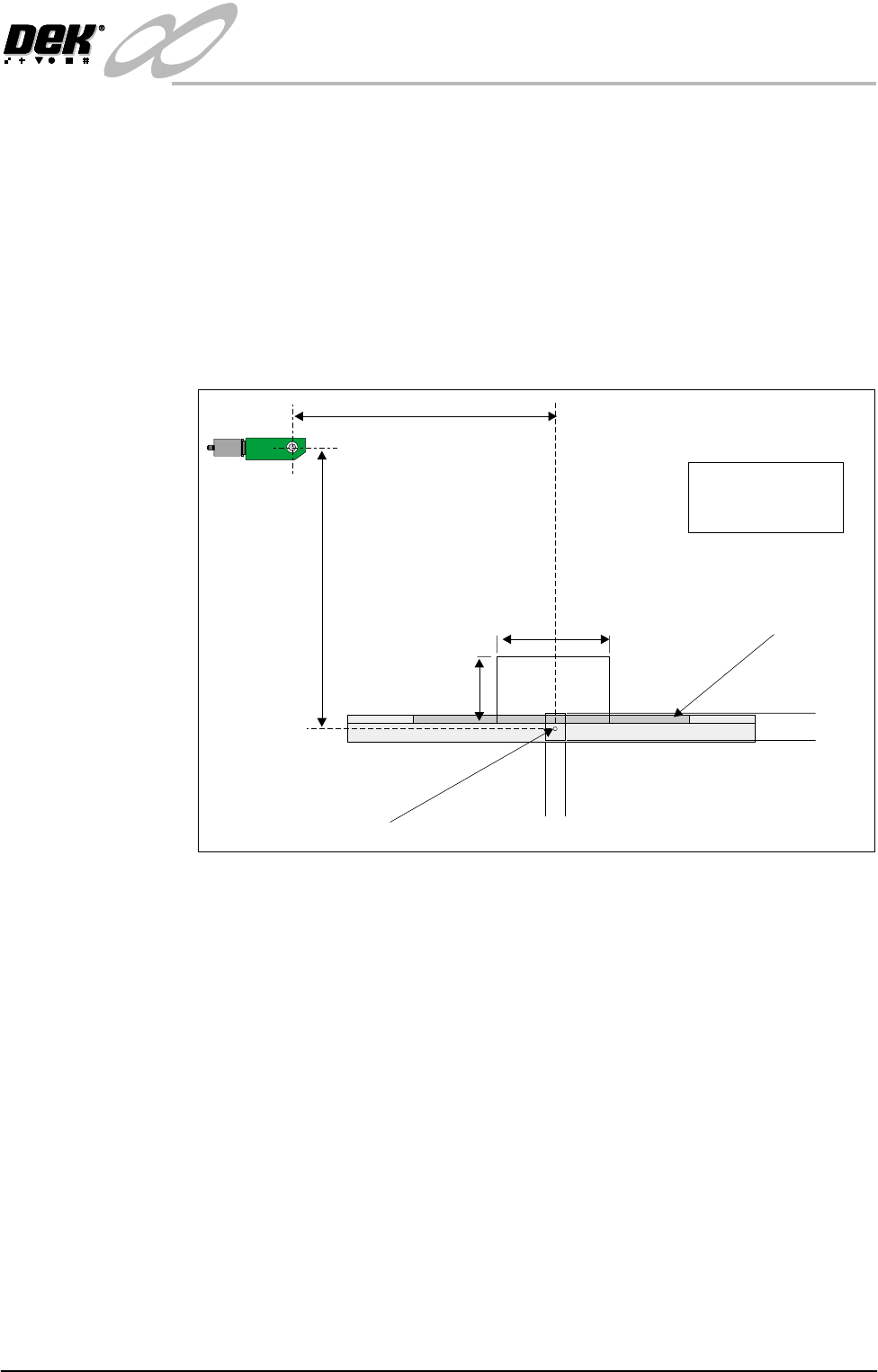
Camera Reference
Position
A white dot is located centrally on the front rail and 10mm back from the board
edge, this is the camera reference position.
The camera is driven to the reference position which is stored in the config.cfg
file as a dimension relative to the home position.
It must lie within the X and Y limits as shown on the Camera Reference Position
Figure below, otherwise the position is not saved.
All camera positions, board stop, fiducials, screen cleaner pick-up are calculated
relative to this point.
Figure 17-8 Camera Reference Position
X Reference
Optic Centre at Home
Y Reference
200mm
100mm
560mm
590mm
320mm 340mm
X Limits
Board Clamp
Front Rail
Reference Position
Y Limits
PULNIX
TM-6EX
Eg.
X = 335mm
Y = 572mm