00191174-01.pdf - 第5页
User’s Manual Test Program S ITEST 0 Introduction Software Version 10.xx Edition 03/98 0.1 Starting of the Test Program 0 - 1 0 Introduction NOTE The pr esent Use r’s Man ual is ba sed o n SIT EST so ftware versio n 10. …

User’s Manual Test Program SITEST
Software Version 10.xx Edition 03/98
0 - II

User’s Manual Test Program SITEST 0 Introduction
Software Version 10.xx Edition 03/98 0.1 Starting of the Test Program
0 - 1
0 Introduction
NOTE
The present User’s Manual is based on SITEST software version 10.01.
WARNING
∆
!
∆
!
This test program may only be operated by staff members of SIEMENS AG PL EA V Service, or specially
trained customer personnel. Improper use of this test program will result in severe damage to the machine
and will pose a hazard to the operating personnel.
0.1 Starting of the Test Program
●
Insert the SITEST start diskette (boot diskette) for "S15 / F" automatic placement machines into the 3.5"
disk drive in the control unit.
●
Turn on the machine. The station computer starts booting.
●
Then start the SITEST program. After a short while, the main menu of the test program will appear (in the
language version you installed) on the screen.
NOTE
The machine type (SIPLACE 80S15 or 80F3) and the desired language are selected during the installa-
tion of the SITEST software.
0.1.1 Terminating the Test Program
●
Remove the SITEST start diskette from the disk drive.
●
Turn the machine off and back on again.
I/O ports
Axes
Vacuum
Motor contr.board
Vision system
Mapping
Continuous run
Head functions
Functions
Gantry positions
Head reference run
Gantry refer. run
Select gantry
File manager
Miscellaneous
Teach menu
SITEST 80S/F Version 10.xx Date
0 Introduction User’s Manual Test Program SITEST
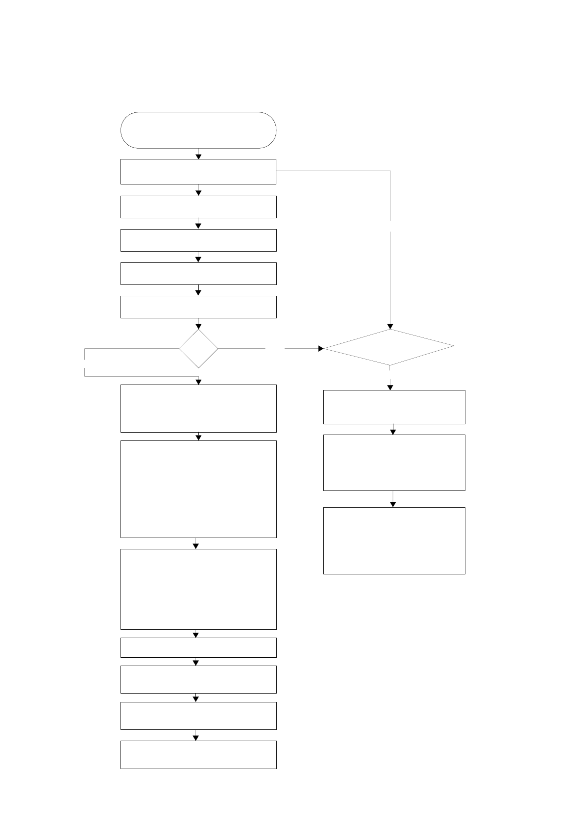
0.2 Flow chart for the calibration procedure Software Version 10.xx Edition 03/98
0 - 2
0.2 Flow chart for the calibration procedure
Start calibration
2. calibrate pcb camera
3. calibrate component camera
4. measure segment offset
5. offset pcb/component camera
6. calibrate machine zero point
(check travel range of the main
axes after a mechanical change)
7. IC camera
(menu meas. focus of camera)
a) adjust focus
b) measure z- delta
c) calibrate IC camera
d) offset pcb/IC-camera
8. FC camera
(menu meas. focus of camera)
a) adjust focus
b) measure z- delta
c) calibrate FC camera
9. calibrate coplanmodul
10. feeder table
calibrate track 1 a. 120
11. calibrate nozzle changer
revolver head
12. calibrate nozzle changer
IC head
80S
6. calibrate machine zero
points (both gantries)
calibrate
2. gantry
yes
yes
no
7. feeder table with gantry1
and gantry 2
calibrate track 1 a. 120
8. nozzle changer revolver-
head
(calibrate both gantries z, x
and y)
no
1. move to calibration piece