Printer 600 Machine Controller.pdf - 第10页
0$&+,1( &21752//( 5 1(;7029( &$5' 6.10 Technical Reference Manual Chapter Issue 4 May 03 Analog to Digit al Converter Analog inpu ts ar e fed to MAX 180 devices, a n eight chann el, t welve bit multipl…
0$&+,1(&21752//(5
1(;7029(&$5'
Chapter Issue 4 May 03 Technical Reference Manual 6.9
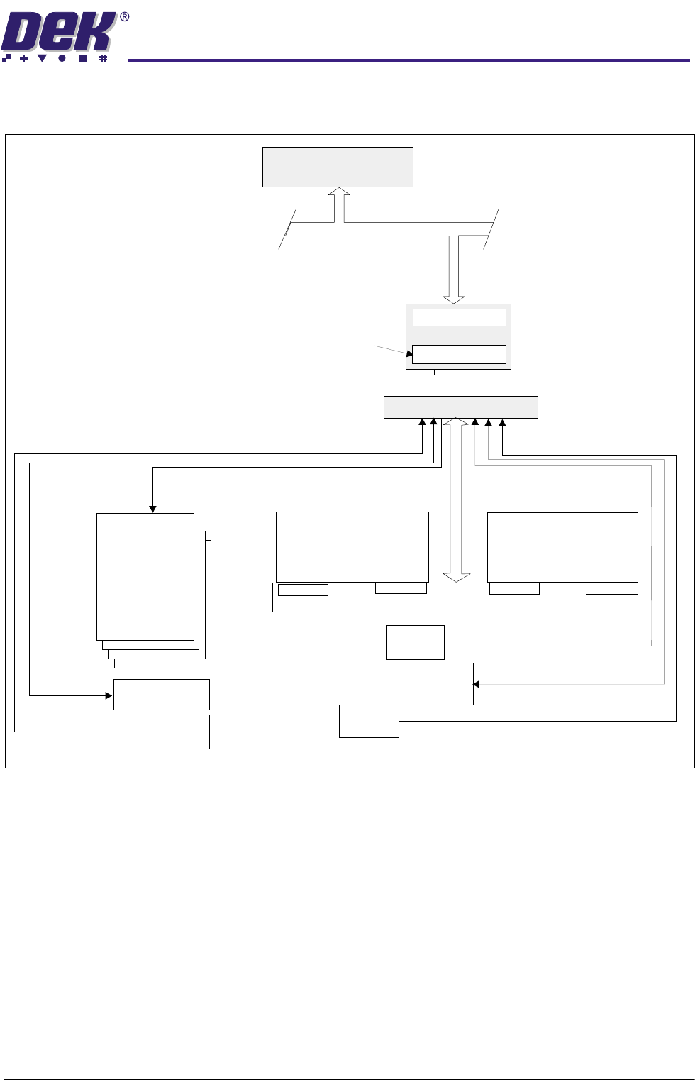
NextMove Block Diagram
CAUTION
ANTI-STATIC HANDLING.
Standard precautions must be adhered to when
handling electronic cards and configuring and inserting into the enclo-
sures.
PC
Single Board Computer
ISA BUS
NextMove
NextMove Breakout
CAN
Motion Control
‘C’ Program Storage
MultiMove X12
MultiMove X13
MultiMove Backplane
Dual Port RAM
512K RAM
Servo Drive
Axis0-3
MUX/Monitor
Pressure,Temperature, Humidity
Switches, Interlocks, Error
Upline/Downline
Sensors
Analog
Sensors
MIU or
FMI Pod
I/O
Digital
Sensors
Servo Motor
Encoders
MUX Control
Axis Homes
Servo Demand
0$&+,1(&21752//(5
1(;7029(&$5'
6.10 Technical Reference Manual Chapter Issue 4 May 03
Analog to Digital
Converter
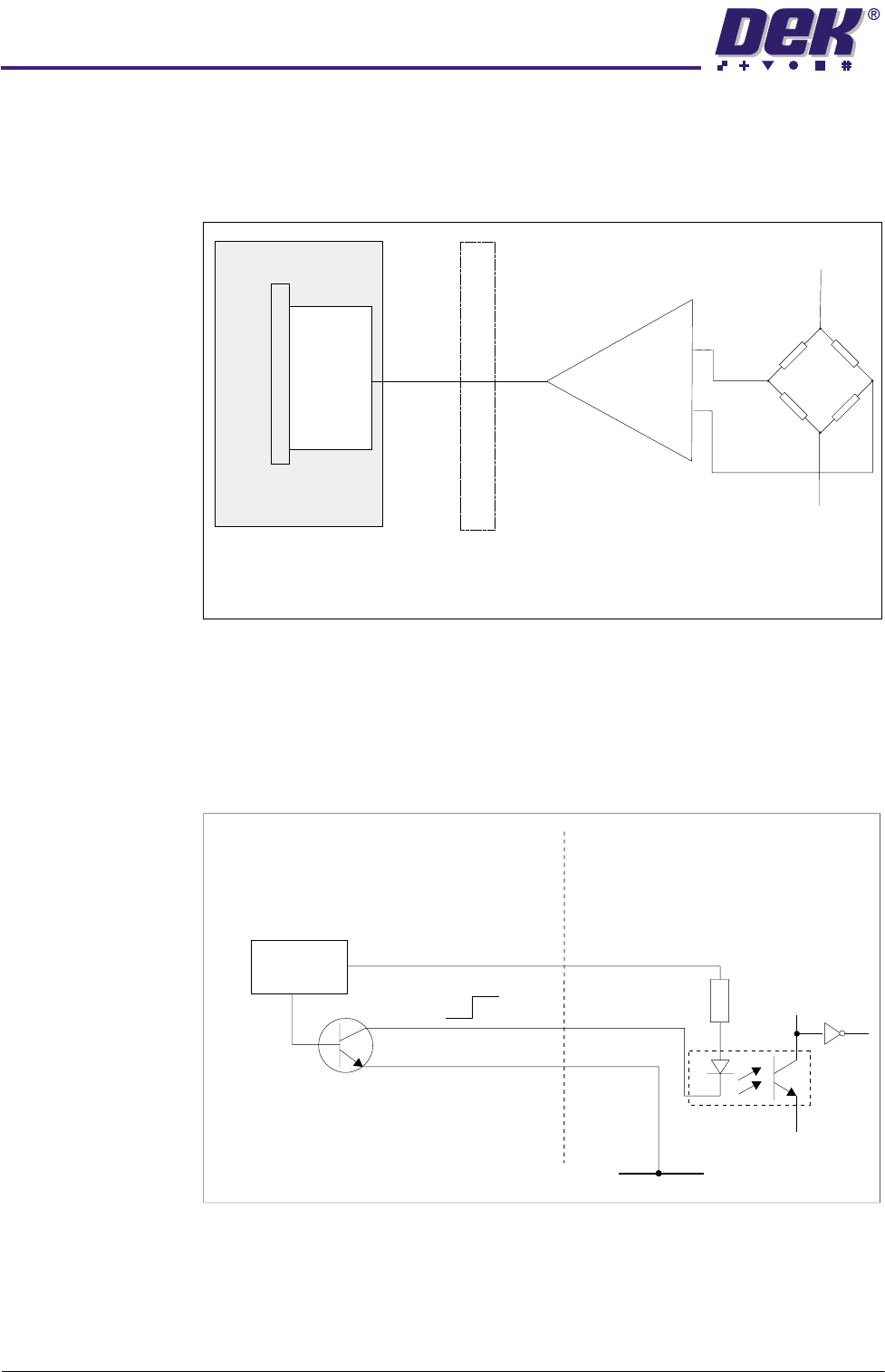
Analog inputs are fed to MAX 180 devices, an eight channel, twelve bit
multiplexed analog to digital converter. The NextMove card is capable of
operating with either a bipolar input voltage or a unipolar input voltage and
selection of this feature is made under software control.
Figure 6-5 Sample ADC Circuit
Digital Inputs The digital inputs are selected as opto-isolated NPN circuits. The signal must
be present for a minimum of 1ms (one software scan) for the input to be
accepted by the application program.
An example of a digital input is shown below:
Figure 6-6 Digital Input Sample
Sensor
+V
-V
NextMove
Breakout
NextMove Card
Digital
Out
Analog In
Differential
Amplifier
-Signal In
+Signal In
Out
MAX 180
ADC
Hall Effect (Home) Switch
NextMove Digital Input
V+ (User)
Opto-Isolator
2K
0V
12V
12V
0V
0V
Signal
V+
Control
Circuit
0$&+,1(&21752//(5
1(;7029(&$5'
Chapter Issue 4 May 03 Technical Reference Manual 6.11
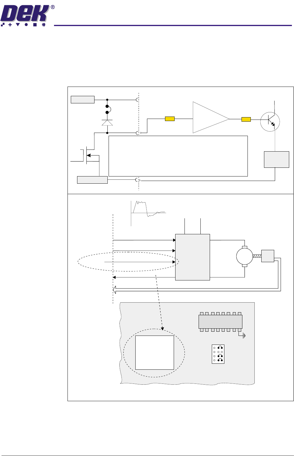
Digital Outputs The twelve digital outputs are opto-isolated open collector type arranged as a
bank of eight and a bank of four. The bank of eight are NPN Darlington pairs,
the bank of four are FET’s which supply the servo enable control of the servo
drive cards and the stepper MUX control signals.
An example of a servo enable control digital output is shown below:
Figure 6-7 Digital Output Sample
Enable In
LED
Link
Z
Enable Out
LED
NextMove Card
FET
*
**
**
User Gnd
For the bank of 8, an NPN Darlington Pair is used instead
of an FET.
For the bank of 8, Link Z is replaced with Link X, which is
not fitted enabling the voltage at the collector to be
different than 12V.
*
ENABLE
IC
Load
Servo Drive
Encoder
NextMove
Dig O/P
(FET)
Dig I/P
Servo 0
Input
Servo 0 Demand +VE
44V
AC2
44V
AC1
+VE
-VE
Servo 0 Enable
Servo 0 Error
Servo 0 Demand -VE
M
Demand
+10V
-10V
ZYXW
1
U37
Com
Part of NextMove Card
ULN 2803
FET
Daughterboard
U38
User V+
12V