Printer 600 Machine Controller.pdf - 第9页
0$&+ ,1(&21752 //(5 1(;7029( &$5' Chapter Issue 4 May 03 Technical Reference Manual 6.9 NextMove Block Diagram CAUTION ANTI-ST ATIC HANDLING. St andard precautions must be adhered to when handling el e…

0$&+,1(&21752//(5
1(;7029(&$5'
6.8 Technical Reference Manual Chapter Issue 4 May 03
Safety Features The NextMove card incorporates many safety features:
• A Limit Error signal is generated at the end of travel limits.
• The maximum permissible following error, before cutting power to the
motors, can be pre-set.
• A Control Stop input is used to bring all axes to a controlled stop.
• An External Error input is used to bring all axes to a quick stop, ie E Stop.
• The system watchdog (Jumper L) resets the processor in the event of a
major operating firmware malfunction.
Change-over Relay A change-over relay which is energized under software control is included on
the NextMove card to provide a volt free contact, it is used to provide the
software controlled E Stop. The relay is controlled by a latch which is cleared
during reset of the card. Reset occurs on power down, watchdog error or under
control of the PC. Reset is indicated by all three LEDs being illuminated at the
same time.
0$&+,1(&21752//(5
1(;7029(&$5'
Chapter Issue 4 May 03 Technical Reference Manual 6.9
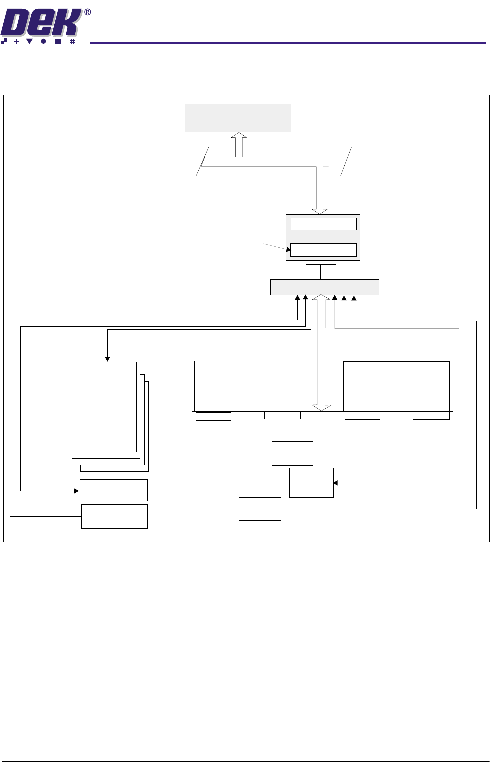
NextMove Block Diagram
CAUTION
ANTI-STATIC HANDLING.
Standard precautions must be adhered to when
handling electronic cards and configuring and inserting into the enclo-
sures.
PC
Single Board Computer
ISA BUS
NextMove
NextMove Breakout
CAN
Motion Control
‘C’ Program Storage
MultiMove X12
MultiMove X13
MultiMove Backplane
Dual Port RAM
512K RAM
Servo Drive
Axis0-3
MUX/Monitor
Pressure,Temperature, Humidity
Switches, Interlocks, Error
Upline/Downline
Sensors
Analog
Sensors
MIU or
FMI Pod
I/O
Digital
Sensors
Servo Motor
Encoders
MUX Control
Axis Homes
Servo Demand
0$&+,1(&21752//(5
1(;7029(&$5'
6.10 Technical Reference Manual Chapter Issue 4 May 03
Analog to Digital
Converter
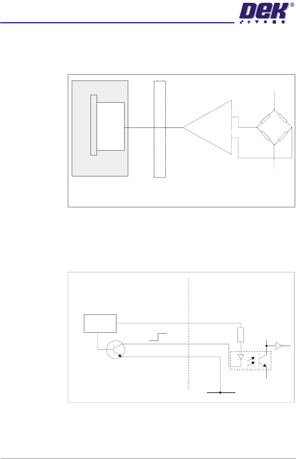
Analog inputs are fed to MAX 180 devices, an eight channel, twelve bit
multiplexed analog to digital converter. The NextMove card is capable of
operating with either a bipolar input voltage or a unipolar input voltage and
selection of this feature is made under software control.
Figure 6-5 Sample ADC Circuit
Digital Inputs The digital inputs are selected as opto-isolated NPN circuits. The signal must
be present for a minimum of 1ms (one software scan) for the input to be
accepted by the application program.
An example of a digital input is shown below:
Figure 6-6 Digital Input Sample
Sensor
+V
-V
NextMove
Breakout
NextMove Card
Digital
Out
Analog In
Differential
Amplifier
-Signal In
+Signal In
Out
MAX 180
ADC
Hall Effect (Home) Switch
NextMove Digital Input
V+ (User)
Opto-Isolator
2K
0V
12V
12V
0V
0V
Signal
V+
Control
Circuit