Printer 600 Machine Controller.pdf - 第21页
0$&+ ,1(&21752 //(5 08/7,029( Chapter Issue 4 May 03 Technical Reference Manual 6.21 Universal Driv ers The universal driv ers descr ibed belo w form the basis f or both the t otem and source drive output s. The…
0$&+,1(&21752//(5
08/7,029(
6.20 Technical Reference Manual Chapter Issue 4 May 03
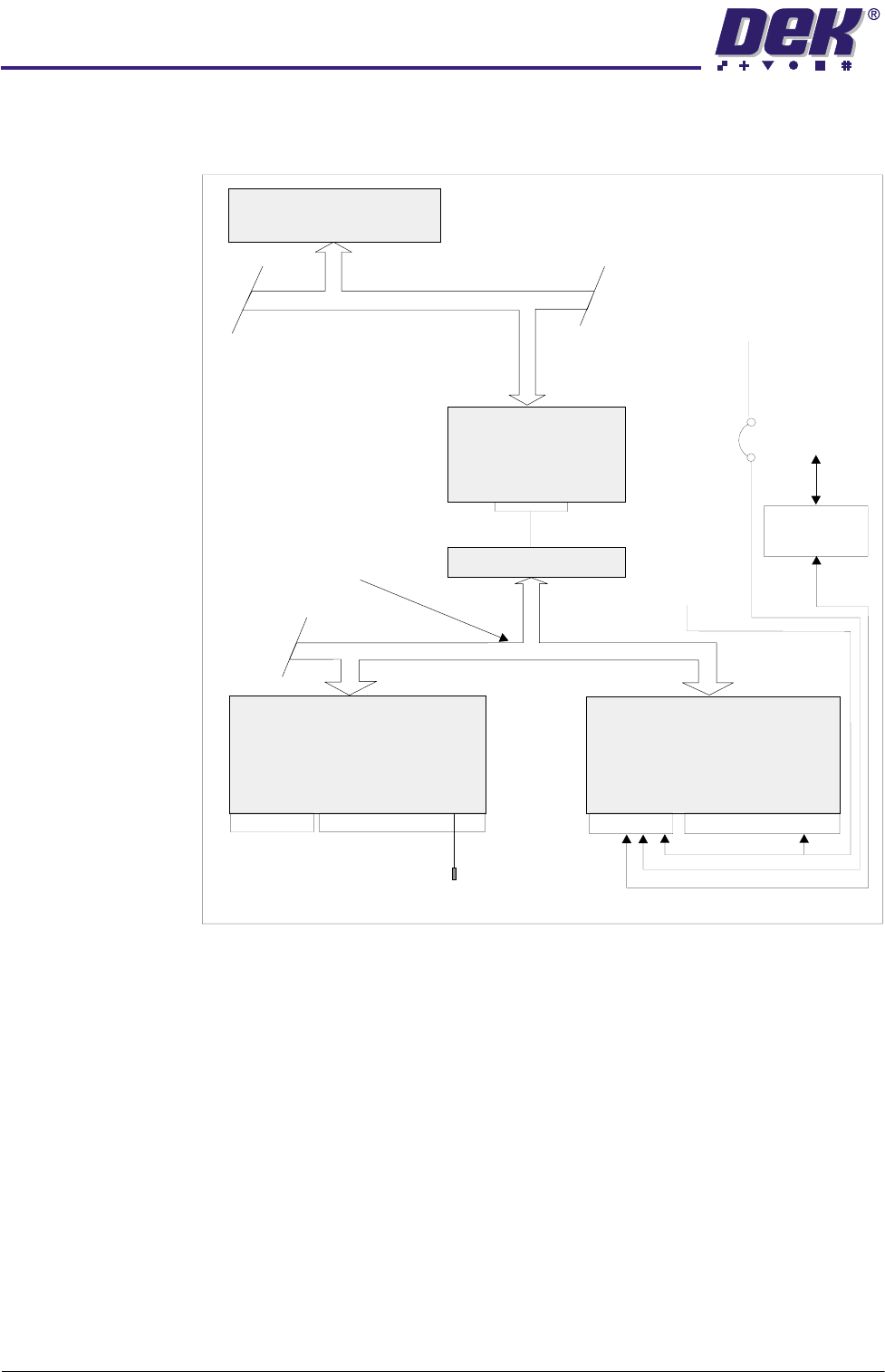
MultiMove Block
Diagram
The MultiMove cards are controlled via the CAN network by the NextMove
cards.
Figure 6-15 MultiMove Interface
NOTE
1. JP1 is a link to DIG IN 9 and it is fitted to the MultiMove Backplane. The
machine software interrogates this function and determines the correct machine
software to run. This link should not be removed.
2. See the MultiMove tables for a complete listing of the MultiMove inputs and
outputs.
CAUTION
ANTI-STATIC HANDLING.
Standard precautions must be adhered to when
handling electronic cards and configuring and inserting into the enclo-
sures.
Single Board Computer
ISA BUS
NextMove
NextMove Breakout
CAN
Controller Area Network
Peripheral I/O Control
MultiMove X12
MultiMove X13
24V US
24V _SW
+12V_US
5V LOGIC
MIU
Upline/Downline
Machine
Machine
Software I/P
JP1
See
Note 1
16 I/P’s 8 O/P’s 8 O/P’s
16 I/P’s 8 O/P’s 8 O/P’s
SK13B
SK13A
SK12B
Source 0
P8
Rising Table Brake
SK12A
Source 0
to Source 7
Totem 0
to Totem 7
IN0 to INF
0$&+,1(&21752//(5
08/7,029(
Chapter Issue 4 May 03 Technical Reference Manual 6.21
Universal Drivers The universal drivers described below form the basis for both the totem and
source drive outputs.
The PBD 3548/1 device is a source driver which has an output stage that is
switched on or off according to the voltage at its input. A high input signal
switches the transistor off, if the input is left open then it is detected as a low
signal.
The PBD 3545/1 is a sink driver and it also has an output stage that is switched
on or off according to the voltage at its input. A low input signal switches the
transistor off, if the input is left open then it is detected as a high signal.
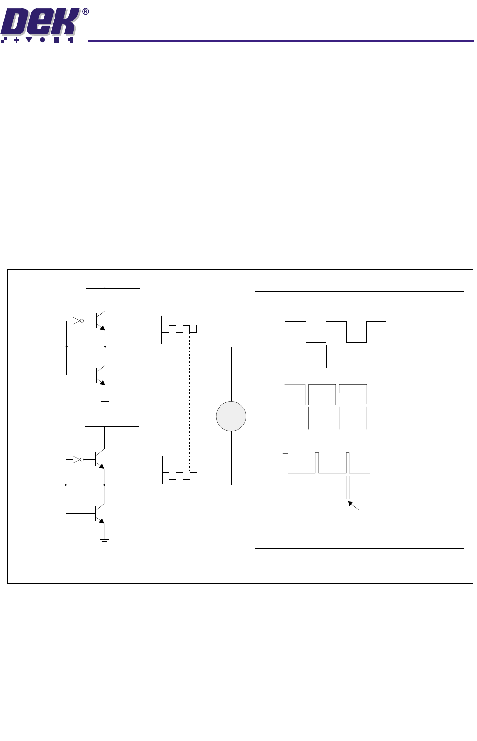
Totem Drivers The totem driver uses a pair of devices in a source/sink (totem pole) arrange-
ment. This configuration is used to drive the 24V motors using pulse width
modulated (PWM) techniques. To drive a motor in both directions ie, a transport
belt, a dual driver arrangement of the type shown below is used.
Figure 6-16 Bipolar (Totem) as a PWM Driver
ON
Period
ON
Time
Medium speed
OFF
ON
ON
Period
Period
ON
Time
ON
Time
High speed
Slow speed
OFF
OFF
Bi-directional
Speed Control
eg. Belts
Vcc +24V
PBD 3548\1
(PWM)
Vcc +24V
PBD 3548\1
PBD 3545\1
CH 0
CH 1
I/P from S/W
I/P from S/W
PBD 3545\1
M
NOTE
PWM CH1 is the inverse of PWM CH0
(PWM)
-1
0$&+,1(&21752//(5
08/7,029(
6.22 Technical Reference Manual Chapter Issue 4 May 03
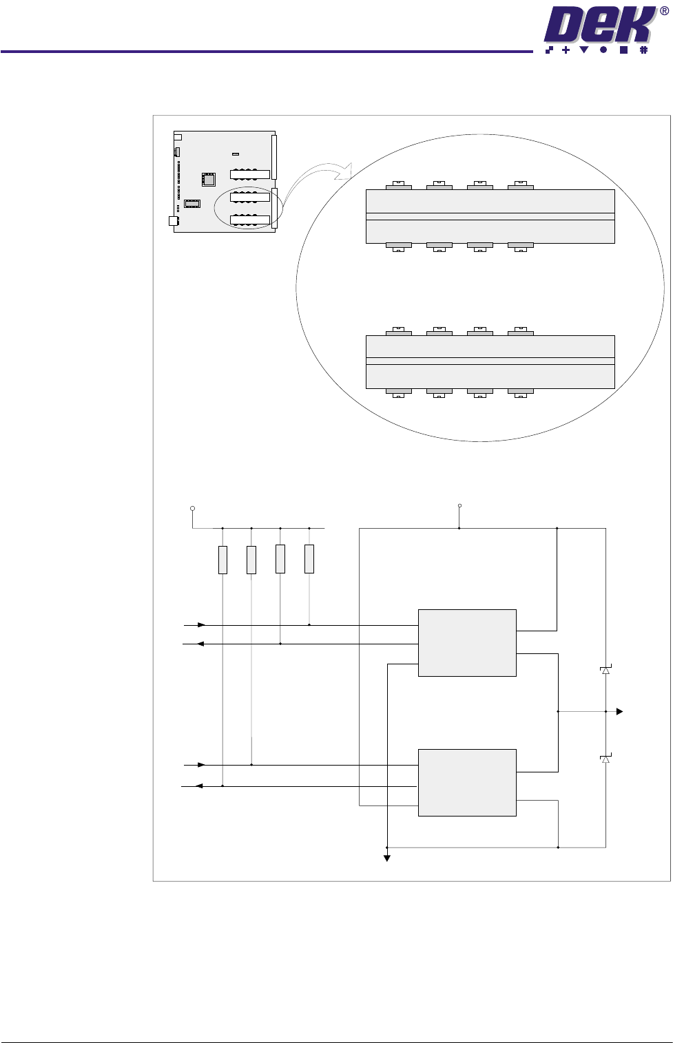
Eight Totem outputs are derived from the devices shown below.
Figure 6-17 Typical Totem Drive Schematic
U200
IN
2
1
3
ERR
GND
V+
OUT
4K7
4K7
4K7 4K7
V Isol
MultiMove Card
V Power
Gnd Isol
PBD 3548/1
PBD 3545/1
U201
Totem 0
IN
5
2
4
5
3
1
4
ERR
GND
V+
OUT
U208 U210 U212 U214
U209 U211 U213 U215
U200 U202 U204 U206
PBD 3548/1
PBD 3548/1
PBD 3545/1
PBD 3545/1
U201
Totem 0
Totem 2
Totem 3Totem 1
Totem 4
Totem 6
Totem 7Totem 5
Totem 4 Totem 6
Totem 7Totem 5
Totem 0 Totem 2
Totem 3Totem 1
U203 U205 U207