Printer 600 Machine Controller.pdf - 第17页
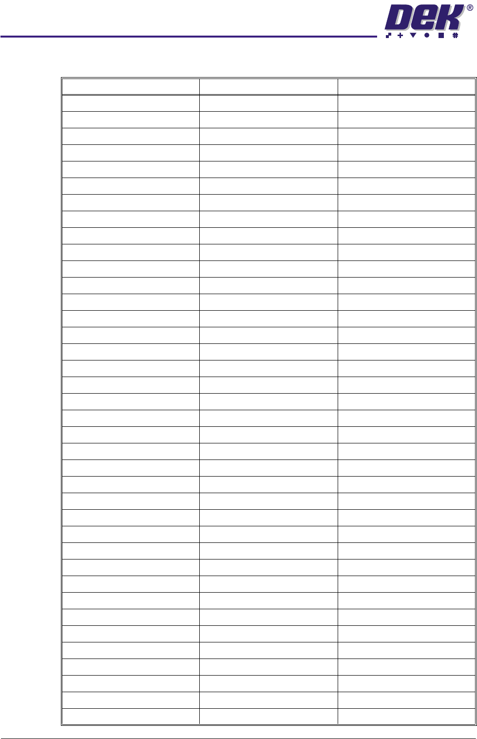
0$&+ ,1(&21752 //(5 1(;7029( &$5' Chapter Issue 4 May 03 Technical Reference Manual 6.17 Figure 6-12 Sample of Next Move Brea kout Wiri ng PIN 39 DIG .IN.7 PIN 77 ¦ PIN 78 PIN 40 DIG .IN.8 PIN 40 DIG .…
0$&+,1(&21752//(5
1(;7029(&$5'
6.16 Technical Reference Manual Chapter Issue 4 May 03
NextMove Breakout Inputs and Outputs
Connector M19PL15 Connector M19SK16 Connector M19PL17
PIN 1 ANALOG GND PIN 1 ¦ PIN 2 PIN 2 ADC0
PIN 2 ADC1 PIN 3 ¦ PIN 4 PIN 1 ADC2
PIN 3 ADC3 PIN 5 ¦ PIN 6 PIN 4 ADC4
PIN 4 ADC5 PIN 7 ¦ PIN 8 PIN 3 ADC6
PIN 5 ADC7 PIN 9 ¦ PIN 10 PIN 6 DAC0
PIN 6 DAC1 PIN 11 ¦ PIN 12 PIN 5 DAC2
PIN 7 DAC3 PIN 13 ¦ PIN 14 PIN 8 ANALOG GND
PIN 8 DOP0 PIN 15 ¦ PIN 16 PIN 7 DOP1
PIN 9 DOP2 PIN 17 ¦ PIN 18 PIN10 DOP3
PIN 10 DOP4 PIN 19 ¦ PIN 20 PIN 9 DOP5
PIN 11 DOP6 PIN 21 ¦ PIN 22 PIN 12 DOP7
PIN 12 DOP8 PIN 23 ¦ PIN 24 PIN 11 DOP9
PIN 13 DOP10 PIN 25 ¦ PIN 26 PIN 14 DOP11
PIN 14 USER V+ PIN 27 ¦ PIN 28 PIN 13 USR GND
PIN 15 CAN WIRE+ PIN 29 ¦ PIN 30 PIN 16 CAN WIRE-
PIN 16 !EXT.INT.U PIN 31 ¦ PIN 32 PIN 15 ENCO.1
PIN 17 ENCO!! PIN 33 ¦ PIN 34 PIN 18 ENCO.B
PIN 18 ENCO!B PIN 35 ¦ PIN 36 PIN 17 ENCO.A
PIN19 ENCO!A PIN 37 ¦ PIN 38 PIN 20 ENC1.1
PIN 20 ENCO1!! PIN 39 ¦ PIN 40 PIN 19 ENC1.B
PIN 21 ENC.1 !B PIN 41 ¦ PIN 42 PIN 22 ENC1.A
PIN 22 ENC1 !A PIN 43 ¦ PIN 44 PIN 21 ENC2.1
PIN 23 ENC2!! PIN 45 ¦ PIN 46 PIN 24 ENC2.B
PIN 24 ENC2 !B PIN 47 ¦ PIN 48 PIN 23 ENC2.A
PIN 25 ENC2 !A PIN 49 ¦ PIN 50 PIN 26 ENC3.1
PIN 26 ENC3!! PIN 51 ¦ PIN 52 PIN 25 ENC3.B
PIN 27 ENC3 !B PIN 53 ¦ PIN 54 PIN 28 ENC3.A
PIN 28 ENC3 !A PIN 55 ¦ PIN 56 PIN 27 USR V+
PIN 29 PULSE 0 PIN 57 ¦ PIN 58 PIN 30 DIR 0
PIN 30 BOOST 0 PIN 59 ¦ PIN 60 PIN 29 PULSE 1
PIN 31 DIR 1 PIN 61 ¦ PIN 62 PIN 32 BOOST 0
PIN 32 PULSE 2 PIN 63 ¦ PIN 64 PIN 31 DIR 2
PIN 33 BOOST 2 PIN 65 ¦ PIN 66 PIN 34 PULSE 3
PIN 34 DIR 3 PIN 67 ¦ PIN 68 PIN BOOST 3
PIN 35 USER GND PIN 69 ¦ PIN 70 PIN 36 DIG.IN.0
PIN 36 DIG.IN.1 PIN 71 ¦ PIN 72 PIN 35 DIG.IN.2
PIN 37 DIG.IN.3 PIN 73 ¦ PIN 74 PIN 38 DIG.IN.4
PIN 38 DIG.IN.5 PIN 75 ¦ PIN 76 PIN 37 DIG.IN.6
0$&+,1(&21752//(5
1(;7029(&$5'
Chapter Issue 4 May 03 Technical Reference Manual 6.17
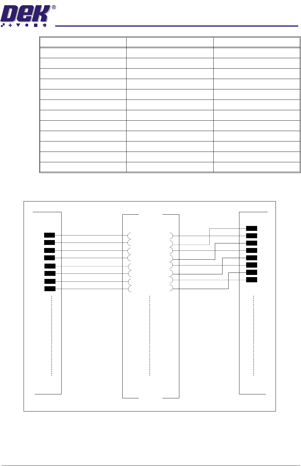
Figure 6-12 Sample of Next Move Breakout Wiring
PIN 39 DIG.IN.7 PIN 77 ¦ PIN 78 PIN 40 DIG.IN.8
PIN 40 DIG.IN.9 PIN 79 ¦ PIN 80 PIN 39 DIG.IN.10
PIN 41 DIG.IN.11 PIN 81 ¦ PIN 82 PIN 42 DIG.IN.12
PIN 42 DIG.IN.13 PIN 83 ¦ PIN 84 PIN 41 DIG.IN.14
PIN 43 DIG.IN.15 PIN 85 ¦ PIN 86 PIN 44 DIG.IN.16
PIN 44 DIG.IN.17 PIN 87 ¦ PIN 88 PIN 43 DIG.IN.18
PIN 45 DIG.IN.19 PIN 89 ¦ PIN 90 PIN 46 DIG.IN.20
PIN 46 DIG.IN.21 PIN 91 ¦ PIN 92 PIN 45 DIG.IN.22
PIN 47 DIG.IN.23 PIN 93 ¦ PIN 94 PIN 48 GND
PIN 48 +5V O/P PIN 95 ¦ PIN 96 PIN 47 GND
PIN 49 +5V O/P PIN 97 ¦ PIN 98 PIN 50 RELAY COM
PIN 50 RELAY N/C PIN 99 ¦ PIN 100 PIN 49 RELAY NO
Connector M19PL15 Connector M19SK16 Connector M19PL17
01
M19SK16
M19PL17
M19PL15
Refer to Drawing 155502 Sh 01 for detail
01
50 50
100
99
0102
0$&+,1(&21752//(5
&$1%86
6.18 Technical Reference Manual Chapter Issue 4 May 03
CAN BUS The Controller Area Network (CAN) is a bus system for machine motion control.
A transceiver for the 1Mbaud rate CAN serial link is fitted to the NextMove card
to enable communication with the two MultiMove cards. The CAN is a 2-wire
data link designed for transmission of small data packets for fast update of axis
position information.
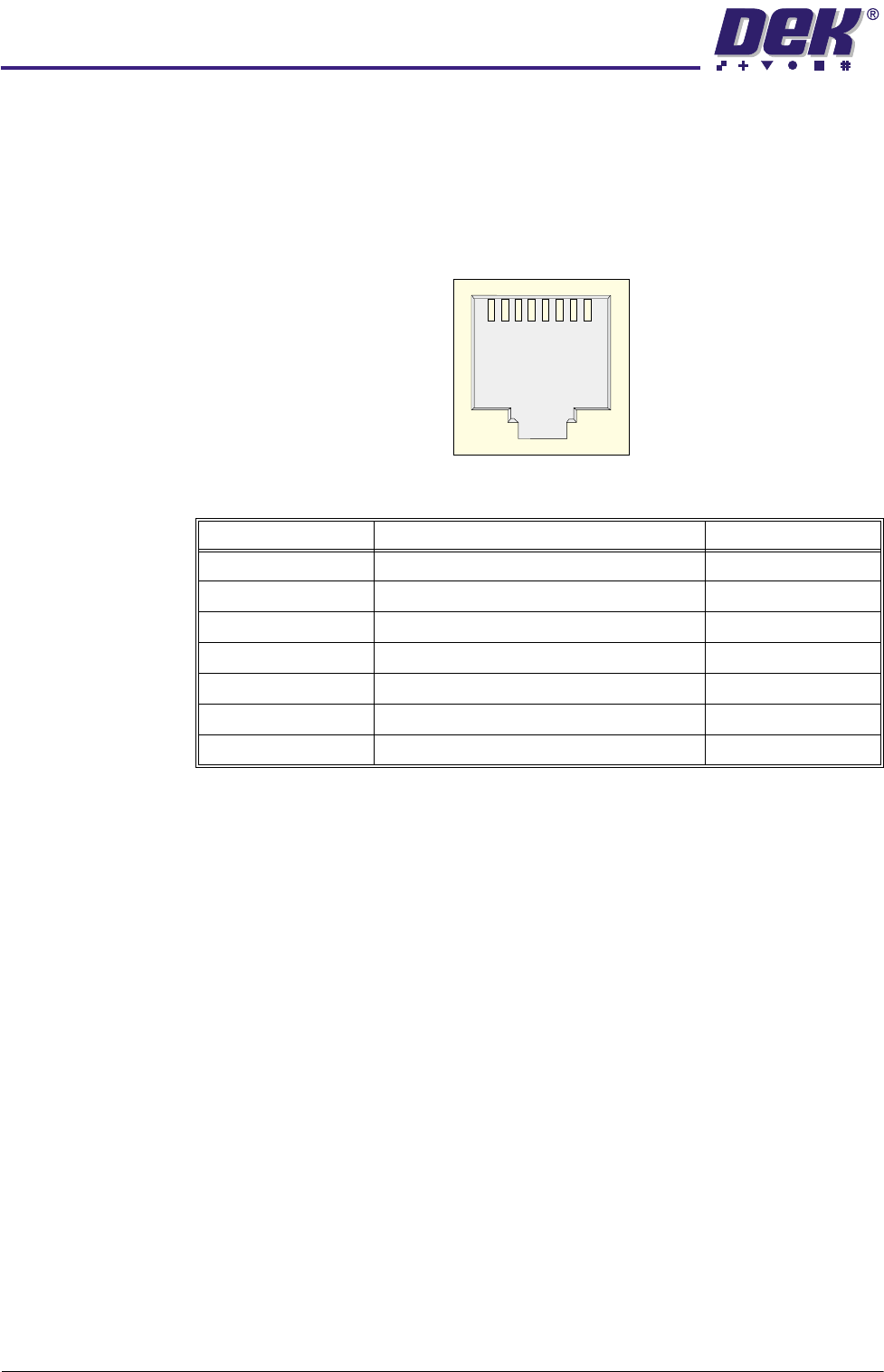
The CAN is presented on two shielded RJ - 45 sockets.
Figure 6-13 CAN Bus Connector
Signal Function RJ-45 Pin
CAN+ CAN Data Signal 1
CAN- CAN Data Signal 2
CAN V+ Power to the CAN Nodes 5
GND Chassis Connection 4
Chassis Screen Pin
N/C No Connection 3,6,7,8
Chassis 360 Degree Cable Screen Shell
1
8