Printer 600 Machine Controller.pdf - 第4页
0$&+,1( &21752//( 5 (/(&7521,& 6(1&/26 85( 6.4 Technical Reference Manual Chapter Issue 4 May 03 Card Placement NOTE *Dual S tepper Card (X6) is configured t o drive a single steppe r motor . Figure…
0$&+,1(&21752//(5
(/(&7521,&6(1&/2685(
Chapter Issue 4 May 03 Technical Reference Manual 6.3
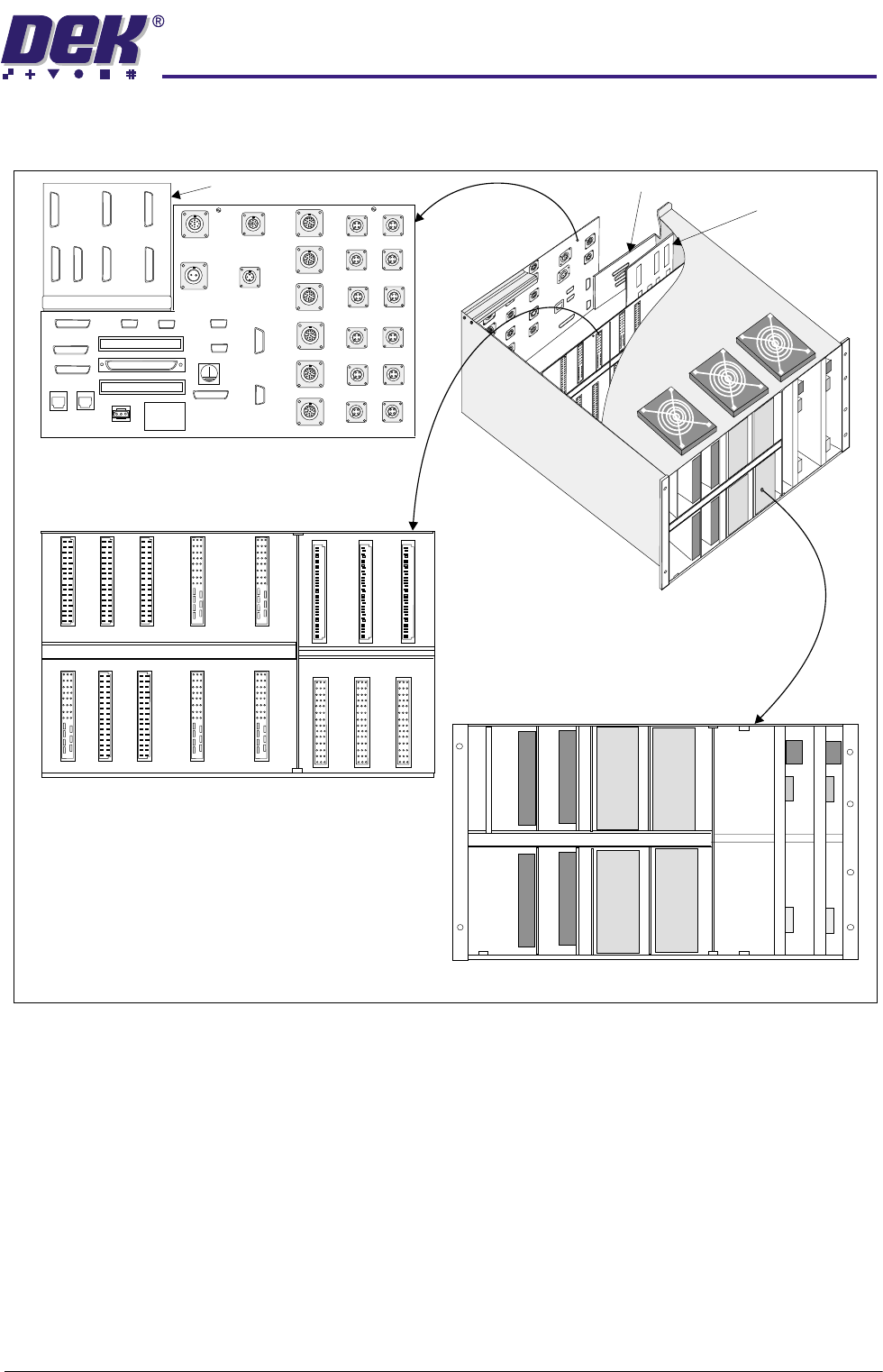
ELECTRONICS ENCLOSURE
Figure 6-1 Electronics Enclosure Layout
NOTE
1. The Electronics Enclosure is housed in the machine in a slider mechanism,
the enclosure can be pulled forward and hinged down for ease of access.
2. The Rear Connector Panel can be folded down for access to the M19
backplane.
CAUTION
ANTI-STATIC HANDLING.
Standard precautions must be adhered to when
handling electronic cards and configuring and inserting into the enclo-
sures.
Rear Connector Panel
(Next Move Breakout and
MultiMove Backplane at Rear)
MultiMove Backplane
NextMove Breakout
MultiMove
M19 Backplane
(Viewed from Front of Enclosure)
X1
X2
X4
X6
X8
X10
X3
X5
X7
X9
X11A
X12A
X13A
X13B
X12BX11B
SERVO AMP
SERVO AMP
MULTIMOVE X11A(24V SW) - IF FITTED
MULTIMOVE X11B(24V SW) - IF FITTED
MULTIMOVE X12A(24V SW)
MULTIMOVE X12B(24V SW)
MULTIMOVE X13B(24V US)
MULTIMOVE X13A(24V US)
SERVO AMP
SERVO AMP
DUAL STEPPER DRIVE
DUAL STEPPER DRIVE
DUAL STEPPER DRIVE
DUAL STEPPER DRIVE
MUX SUPPLIES MONITOR
X
1
X
2
X
4
X
6
X
8
X
1
2
A
MODEL
BATCH NO
BATCH
CENTRE
M19SK45
M19SK39
M19SK38
M19SK37
M19SK36
M19SK35
M19SK34
M19SK33
M19SK32
M19SK31
M19SK27
M19SK26
M19SK30
M19SK29
M19SK28
M19PL24
M19SK22
M19SK05
MMX11 (IN 8-F)
M19SK04
MMX12 (IN 8-F)
M19SK03
MMX13
M19SK02
MIU ‘B’
M19SK01
MIU ‘A’
M19SK07
MMX11 (IN 0-7)
M19SK06
MMX12 (IN 0-7)
M19SK23
M19SK19
M19SK20
M19SK21
M19SK14
M19SK13
M19SK15
M19SK16
M19SK17
M19SK18
M19SK08
M19SK10
M19SK11
M19SK12
M19SK09
M19SK25
M19SK44
M19SK43
M19SK42
M19SK41
M19SK40
M19SK11
M19SK12
Control Enclosure
Card Rack
0$&+,1(&21752//(5
(/(&7521,&6(1&/2685(
6.4 Technical Reference Manual Chapter Issue 4 May 03
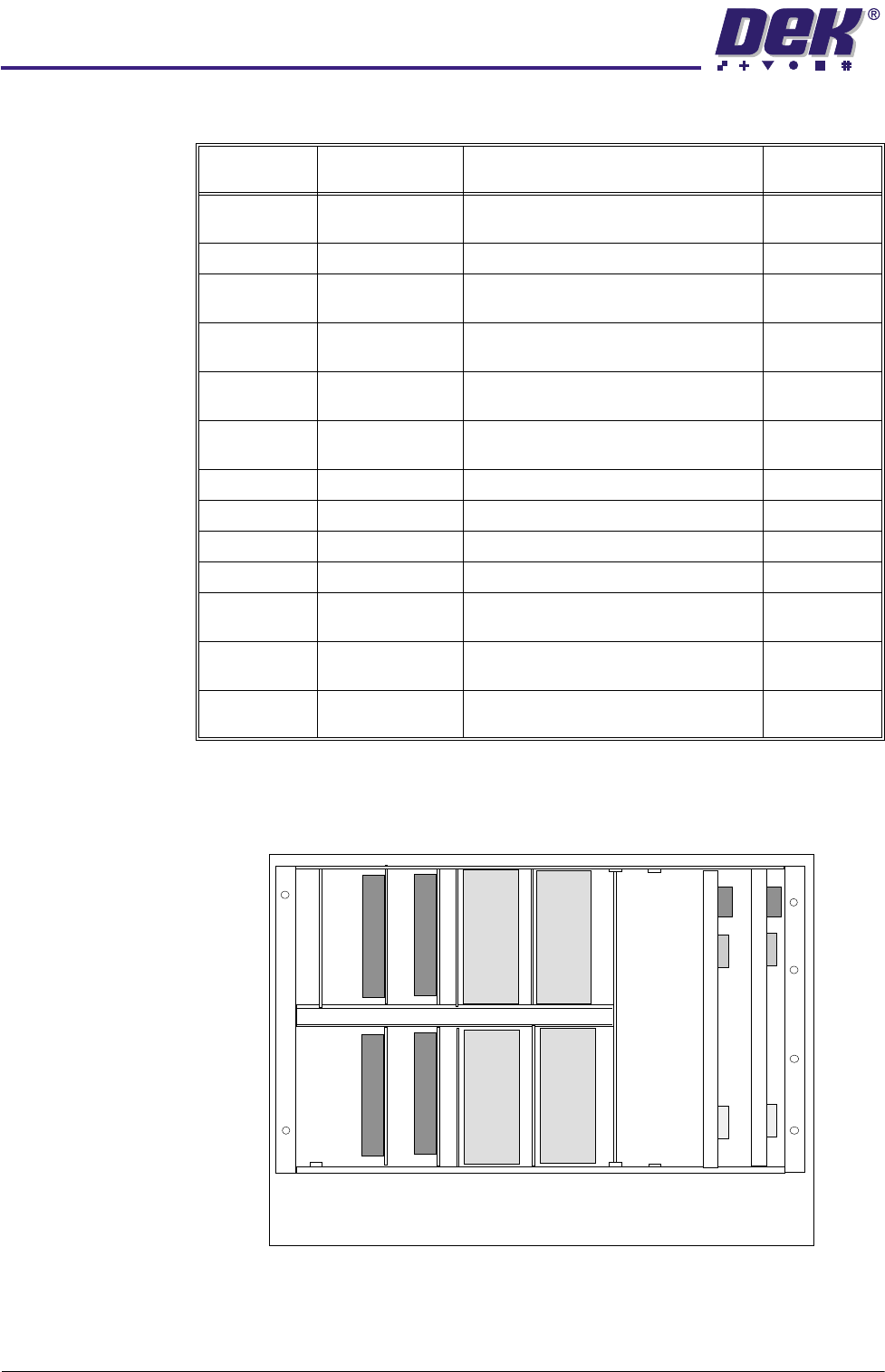
Card Placement
NOTE
*Dual Stepper Card (X6) is configured to drive a single stepper motor.
Figure 6-2 Card Designations
Designation
(Slot)
Card Function Axis
X1 MUX Supplies
Monitor
Stepper motor drives, axis home signals
and supplies monitor function
X2 Head Lift Not Fitted
X3 Dual Stepper Stepper drive to the X fwd and X rear
alignment actuator motors
4, 5
X4 Dual Stepper Stepper drive to the rear squeegee and
the moving rail motors
7 MUX-1
X5 Dual Stepper Stepper drive to the Y alignment actua-
tor and the front squeegee motors
6, 7 MUX-1
X6 *Single Stepper Stepper drive to the paste dispenser
motor
7 MUX-1
X7 Servo Drive Rising table servo motor 0
X8 Servo Drive Camera X servo motor 2
X9 Servo Drive Print carriage servo motor 1
X10 Servo Drive Camera Y servo motor 3
X11 MultiMove
(switched)
Not Fitted
X12 MultiMove
(switched)
Control of inputs/outputs
X13 MultiMove
(unswitched)
Control of inputs/outputs
Card Rack (Front)
X1
X3
X5
X7
X9
X4
X6
X8
X10
X11 X12
X13
X2
0$&+,1(&21752//(5
(;7(51$/&211(&7,216
Chapter Issue 4 May 03 Technical Reference Manual 6.5
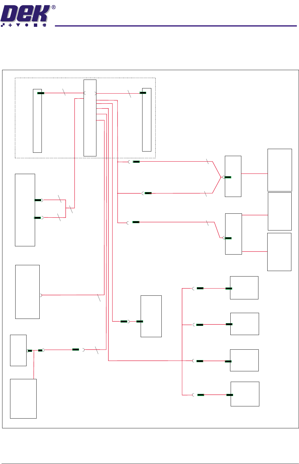
EXTERNAL CONNECTIONS
NextMove Connections
M19SK16
NextMove 100 Way Connector
DIGIN0-23
M19SK08
M19SK10
M19SK21
9SK43
9SK13
M19SK18
Relay
Software E-Stop
Pressure
Amplifier
Temp/Humidity
Sensor
M19SK11
M19SK12
M19SK19
8PL32
10PL06
8PL18
10PL05
Camera
Y
Encoder
Camera
X
Encoder
Print
Carriage
Encoder
Rising
Table
Encoder
M19SK20
M19SK14
M19SK13
MultiMoves
in slots X12 and X13
Servo Stepper
PL31
PL16
CAN 3
CAN 2
CAN 1
M19SK09
PCB A Breakout
Hall Effect and
Through Beam
Opto Switches
Vacuum Tooling
Table Brake
Paste Disp. Sol
Board Position
Sensors
Lane A/B
PCB B Breakout
M19PL15
NextMove Breakout
NextMove
25
25
25
50
50
2
2
12
3
2
M19PL17
NextMove Breakout