Printer 600 Machine Controller.pdf - 第6页
0$&+,1( &21752//( 5 1(;7029( &$5' 6.6 Technical Reference Manual Chapter Issue 4 May 03 NEXTMOVE CARD The NextMove card i s a PC bus motion controlle r that util izes a Digit al Signal Processor for ex…
0$&+,1(&21752//(5
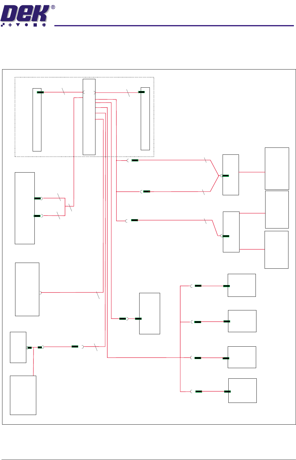
(;7(51$/&211(&7,216
Chapter Issue 4 May 03 Technical Reference Manual 6.5
EXTERNAL CONNECTIONS
NextMove Connections
M19SK16
NextMove 100 Way Connector
DIGIN0-23
M19SK08
M19SK10
M19SK21
9SK43
9SK13
M19SK18
Relay
Software E-Stop
Pressure
Amplifier
Temp/Humidity
Sensor
M19SK11
M19SK12
M19SK19
8PL32
10PL06
8PL18
10PL05
Camera
Y
Encoder
Camera
X
Encoder
Print
Carriage
Encoder
Rising
Table
Encoder
M19SK20
M19SK14
M19SK13
MultiMoves
in slots X12 and X13
Servo Stepper
PL31
PL16
CAN 3
CAN 2
CAN 1
M19SK09
PCB A Breakout
Hall Effect and
Through Beam
Opto Switches
Vacuum Tooling
Table Brake
Paste Disp. Sol
Board Position
Sensors
Lane A/B
PCB B Breakout
M19PL15
NextMove Breakout
NextMove
25
25
25
50
50
2
2
12
3
2
M19PL17
NextMove Breakout
0$&+,1(&21752//(5
1(;7029(&$5'
6.6 Technical Reference Manual Chapter Issue 4 May 03
NEXTMOVE CARD
The NextMove card is a PC bus motion controller that utilizes a Digital Signal
Processor for executing the C instruction language set (The motion control
program). The card controls all motion and input/output for the machine, leaving
the main machine processor free to run the MMI and provide peripheral
interface.
The card sits on the ISA bus of the PC in slot ISA 10 and has the control program
downloaded to it during system boot-up. This program directly controls the main
axes and I/O lines of the machine and indirectly controls the two MultiMove
cards via a Controller Area Network (CAN).
NextMove controls; four servo axes with 12 DAC demand outputs and incre-
mental encoder feedback; four stepper motor axes, three of which are utilized
to provide precision alignment the fourth output is multiplexed giving serial
control of a further five motors.
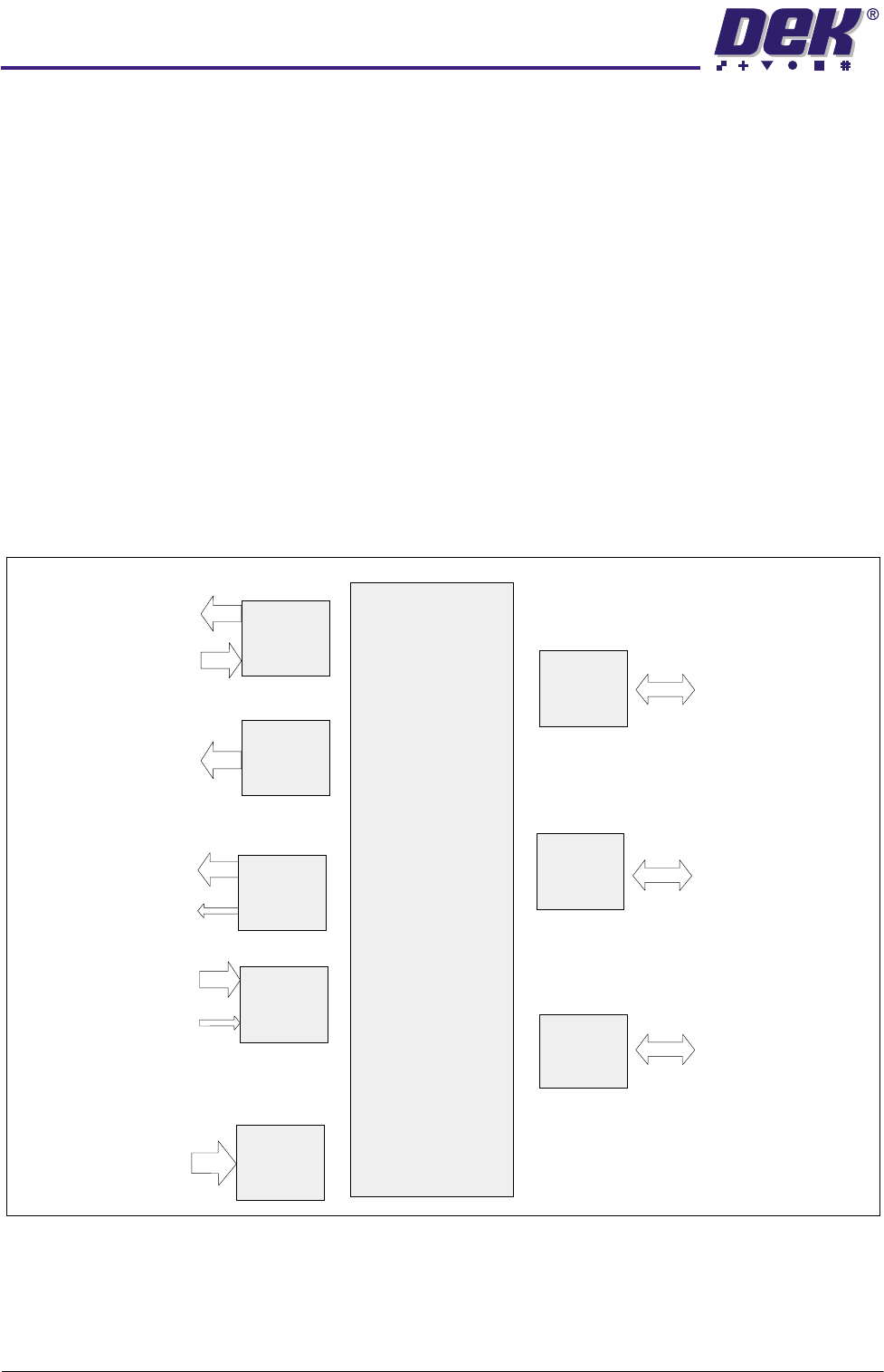
There are several digital or analog input/output signals that are used in the
control function which are routed through and controlled by the NextMove card.
Figure 6-3 NextMove Card Overview
NextMove
Motion Controller
32 Bit Digital
Signal Processor
System
512K RAM
(Motion Control
Program Storage)
4 Servo
Amp Demands
4 Incremental
Encoders
4 Axes of
Closed Loop
Servo Control
4
4
12
Digital
Outputs
12 Digital Outputs
Opto-isolated
Drive Enable Relay
12
24
Digital
Inputs
24 Digital Inputs
Opto-isolated
Hardware Position
Latch and Fast
Interrupt Input
24
4
Analog
Inputs
4x12Bit
Differential
Analog Inputs
4
4 Axes of
Stepper
Motors
4 Step and
Direction Signals
to Control
Stepper Drives
3 Direct, 1 Via MUX
4
ISA/ PCI
Bus Interface
Communication
via
PISA Bus
CAN Bus
Network
Serial
Ports
Industrial Control
Local Area Network
High Speed Card to
Card Data Transfer
0$&+,1(&21752//(5
1(;7029(&$5'
Chapter Issue 4 May 03 Technical Reference Manual 6.7
NextMove Card
Configuration
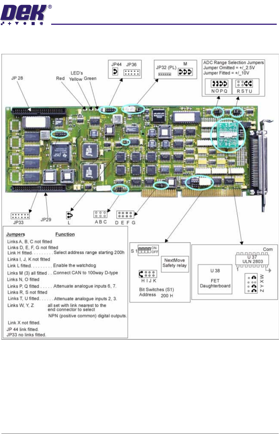
The NextMove card bit switch and jumper settings are shown below:
Figure 6-4 NextMove Card Set Up