Printer 600 Machine Controller.pdf - 第31页
0$&+ ,1(&21752 //(5 67(33(508/7 ,3/(;&$5' Chapter Issue 4 May 03 Technical Reference Manual 6.31 Electrica l Block Diagram Figure 6-22 St epper Multiplexer/ Supplies Monito r Block Diagram In additi o…

0$&+,1(&21752//(5
67(33(508/7,3/(;&$5'
6.30 Technical Reference Manual Chapter Issue 4 May 03
STEPPER MULTIPLEX CARD
Multiplexer
Description
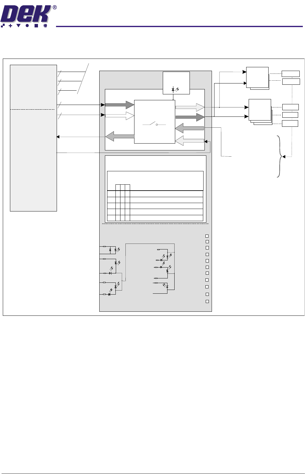
The Stepper Multiplexer is used to control the stepper motors and their sensors
which do not need to be controlled in conjunction with each other ie, not for
alignment purposes. A decoder on the multiplexer board converts the three
input control (CTRL 0-2), the drive signal (MUX Axis Step) and the axis direction
control (MUX Axis Dir) into Step and Direction outputs that are used by the Dual
Stepper Drivers. The axes controlled are; the front and rear squeegees; the
moving rail and the paste dispenser. When the axes are driven to their respec-
tive home position switches, they indicate to the multiplexer board that the axis
has reached home, a single MUX Axis Home signal is fed back to the NextMove
controller. All signals can be monitored on LEDs MUX0 to MUX4, in this way the
single home signal can be deduced for the relevant axis used.
The multiplexer can be thought of as a fully programmable switch where the
controlling inputs CTRL 0-2 determine the logical output state of eight internal
switches in the multiplexer. Only five of these switched outputs are utilized in
this application. Two signals are provided by the NextMove card - Step and
Direction (Dir). By combining (multiplexing) these signals it is possible to
sequentially switch the relevant axis (as determined in machine software) to
enable it to be driven to position. The dual stepper cards condition the signals
to achieve optimum drive results.
0$&+,1(&21752//(5
67(33(508/7,3/(;&$5'
Chapter Issue 4 May 03 Technical Reference Manual 6.31
Electrical Block Diagram
Figure 6-22 Stepper Multiplexer/Supplies Monitor Block Diagram
In addition to the multiplexer function this card also has a set of indicator LEDs
and test points (TP), available on the front panel for supplies voltage monitoring.
CAUTION
POTENTIAL MACHINE DAMAGE.
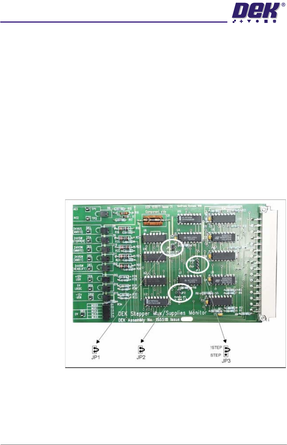
The links fitted to this card control the
drive sequence and step modes for each axis. If the link positions are
changed, the axis can be driven out of sequence and may cause damage
to the machine. The correct link fittings are factory set and should not be
changed.
Alignment (XF, XR, Y)[to alignment Dual Stepper Cards]
CTRL 0-2
MUX Axis Dir
MUX Axis
Home
MUX Axis
Step
3
2
2
2
2
NextMove
4 Output Drives
NextMove I/O
Stepper Multiplexer
Step
Step
Dir
Dir
Dual
Stepper
Dual
Stepper
Home
N/A
Home
Home
Home
Paste Car Home
Rail Home
Rear Sq Home
Front Sq Home
24V USR
+ 12V USR
5V LOGIC
24V US MMX13
AC1
AC2
24V Fans
24V Stepper
24 SW MMX12
24 SW MMX11
24 US MMX13
+12 USR
-12 USR
5V LOGIC
0V US
TP
-12V USR
0V US
Supplies Monitor
AC1
AC2
24V Fans
24V Stepper
24V SW MMX13
NOTE
MMXxx Denotes the MultiMove Axis
24VSW MMX11
Multiplexer
MUX
Monitor
0-4
Multiplexer Control MUX 0-4
Truth Table
Description O/P
CTRL
Bit
2
1
0
000
MUX 0
MUX 1
MUX 2
MUX 3
MUX 4
Front Squeegee
Rear Squeegee
Moving Rail
Paste Carriage
Unused
0
0
1
001
100
011
0$&+,1(&21752//(5
67(33(508/7,3/(;&$5'
6.32 Technical Reference Manual Chapter Issue 4 May 03
Stepper Multiplexer Supplies Monitor Card
The card consists of a supplies monitor section and a multiplexer section. The
multiplexer can be subdivided into three sections the MUX monitor, the Stepper
Line Decoder and the Axis Home Encoder.
The supplies monitor section is labelled with the relevant monitor voltage and
green LEDs are used to indicate that voltages are present. Test points are also
provided so that the voltage of the supplies can be measured with respect to
zero volts.
The MUX monitor consists of 5 yellow LEDs which provide an indication of the
currently selected channel from the stepper line encoder section, this section
decodes the three input control lines to give eight sequential outputs as
described previously. The outputs from the decoder are fed to the dual stepper
driver cards, described later. In addition to this, the MUX axis step signal and
the MUX axis direction signals from the NextMove card are routed into the
stepper line encoder section to establish the step and direction commands on
each of the dual stepper drive cards.
The axis home encoder section enables the signals from the home axis
switches to be directed to the NextMove card, it can establish which axes have
found their home positions relevant to the control sequence.
Figure 6-23 Stepper MUX/Supplies Monitor
CAUTION
ANTI-STATIC HANDLING.
Standard precautions must be adhered to when
handling electronic cards and configuring and inserting into the enclo-
sures.