Printer 600 Machine Controller.pdf - 第22页
0$&+,1( &21752//( 5 08/7,029( 6.22 Technical Reference Manual Chapter Issue 4 May 03 Eight T ot em output s are derived f rom th e device s shown below . Figure 6-17 T ypical T otem D riv e Schematic U200 IN 2 1…
0$&+,1(&21752//(5
08/7,029(
Chapter Issue 4 May 03 Technical Reference Manual 6.21
Universal Drivers The universal drivers described below form the basis for both the totem and
source drive outputs.
The PBD 3548/1 device is a source driver which has an output stage that is
switched on or off according to the voltage at its input. A high input signal
switches the transistor off, if the input is left open then it is detected as a low
signal.
The PBD 3545/1 is a sink driver and it also has an output stage that is switched
on or off according to the voltage at its input. A low input signal switches the
transistor off, if the input is left open then it is detected as a high signal.
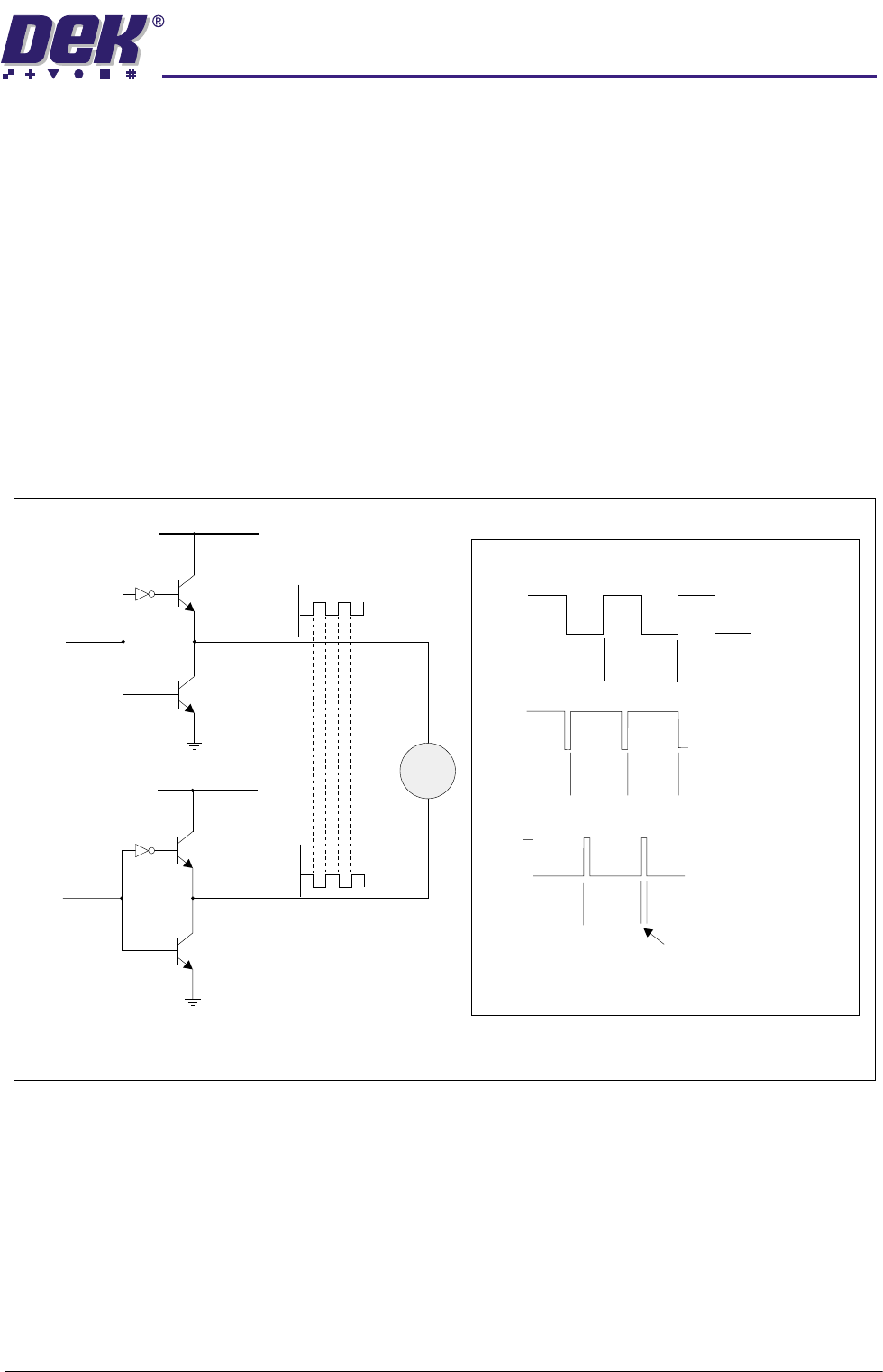
Totem Drivers The totem driver uses a pair of devices in a source/sink (totem pole) arrange-
ment. This configuration is used to drive the 24V motors using pulse width
modulated (PWM) techniques. To drive a motor in both directions ie, a transport
belt, a dual driver arrangement of the type shown below is used.
Figure 6-16 Bipolar (Totem) as a PWM Driver
ON
Period
ON
Time
Medium speed
OFF
ON
ON
Period
Period
ON
Time
ON
Time
High speed
Slow speed
OFF
OFF
Bi-directional
Speed Control
eg. Belts
Vcc +24V
PBD 3548\1
(PWM)
Vcc +24V
PBD 3548\1
PBD 3545\1
CH 0
CH 1
I/P from S/W
I/P from S/W
PBD 3545\1
M
NOTE
PWM CH1 is the inverse of PWM CH0
(PWM)
-1
0$&+,1(&21752//(5
08/7,029(
6.22 Technical Reference Manual Chapter Issue 4 May 03
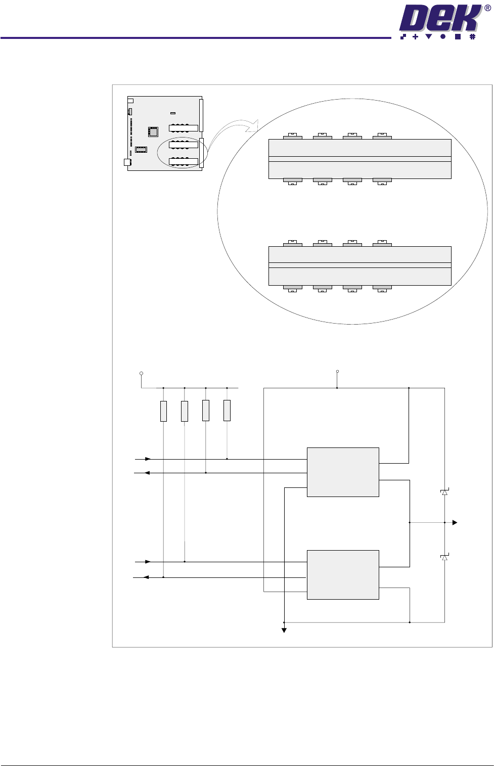
Eight Totem outputs are derived from the devices shown below.
Figure 6-17 Typical Totem Drive Schematic
U200
IN
2
1
3
ERR
GND
V+
OUT
4K7
4K7
4K7 4K7
V Isol
MultiMove Card
V Power
Gnd Isol
PBD 3548/1
PBD 3545/1
U201
Totem 0
IN
5
2
4
5
3
1
4
ERR
GND
V+
OUT
U208 U210 U212 U214
U209 U211 U213 U215
U200 U202 U204 U206
PBD 3548/1
PBD 3548/1
PBD 3545/1
PBD 3545/1
U201
Totem 0
Totem 2
Totem 3Totem 1
Totem 4
Totem 6
Totem 7Totem 5
Totem 4 Totem 6
Totem 7Totem 5
Totem 0 Totem 2
Totem 3Totem 1
U203 U205 U207
0$&+,1(&21752//(5
08/7,029(
Chapter Issue 4 May 03 Technical Reference Manual 6.23
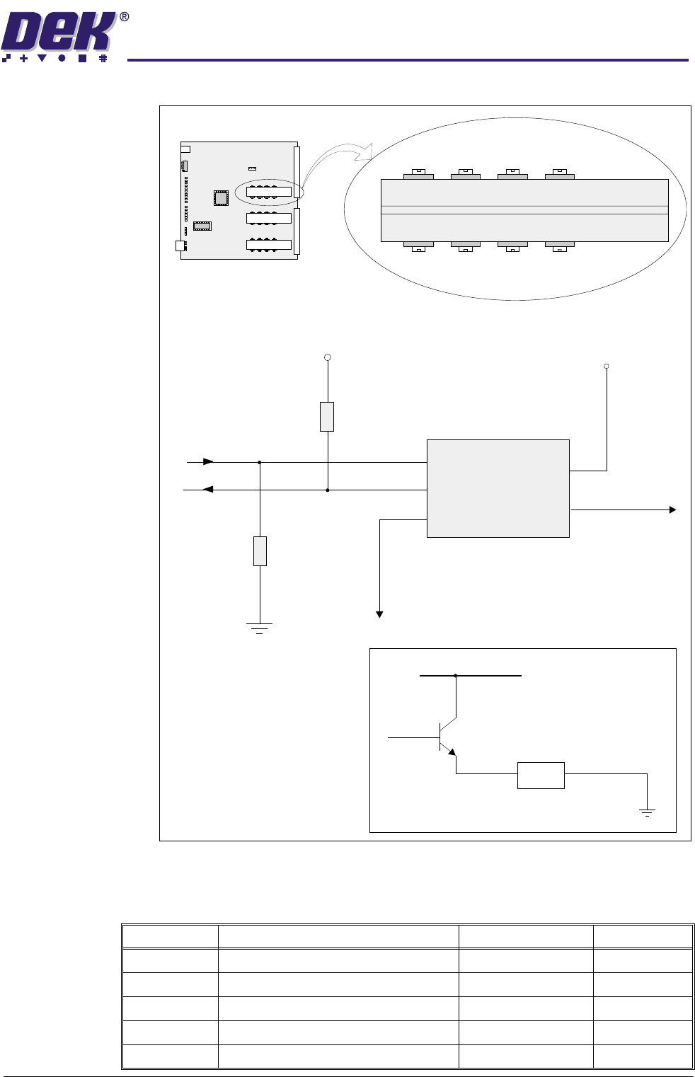
Source Drivers
Figure 6-18 Typical Source Driver Schematic
MultiMove Input and Ouputs
*Tied low, input is from
tristate logic device
which may float during
power ON/reset.
U219 U217 U223 U221
PBD3548/1
PBD3548/1
Source 2 Source 0 Source 6 Source 4
U220 U218 U224 U222
Load
Vcc 24V
Source 0
ON/OFF
eg. Clamps
V Power
*
Device Type 3548/1 Only Shown.
IN
2
1
3
ERR
GND
V+
OUT
Source 0
Gnd Isol
4
5
V Isol
4K7
4K7
Source 3 Source 1Source 7 Source 5
MultiMove Card
Signal Inputs MultiMove X13 Function Destination Device
IN0 Switch - Jog Right 14PL08 8SW2
IN1 Switch - Jog Left 14PL08 8SW1
IN2
IN3 Power On Monitor PCB C - CPL1 PSU
IN4 Switch - Cover Interlock PCB C - CSK6 9SW1