Printer 600 Machine Controller.pdf - 第38页
0$&+,1( &21752//( 5 %5($.287% 2$5'6 6.38 Technical Reference Manual Chapter Issue 4 May 03 BREAKOUT BOAR DS The five br eakout boards, PCB ’ s A t hrough to E and t wo power connect or bracket s are shown …
0$&+,1(&21752//(5
'8$/67(33(5'5,9(
Chapter Issue 4 May 03 Technical Reference Manual 6.37
Motor 1A+ Paste Dispenser Motor
Paste Disp Home Switch - Paste Disp Home M19SK27
Signal Function Destination Source
0$&+,1(&21752//(5
%5($.287%2$5'6
6.38 Technical Reference Manual Chapter Issue 4 May 03
BREAKOUT BOARDS
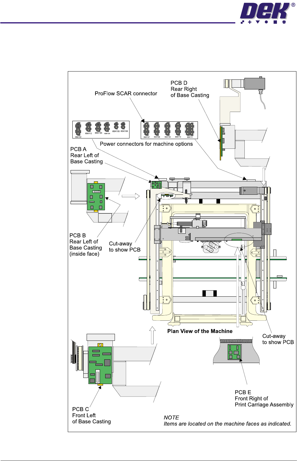
The five breakout boards, PCB’s A through to E and two power connector
brackets are shown in the figure below:
Figure 6-26 Breakout Board Locations
0$&+,1(&21752//(5
%5($.287%2$5'6
Chapter Issue 4 May 03 Technical Reference Manual 6.39
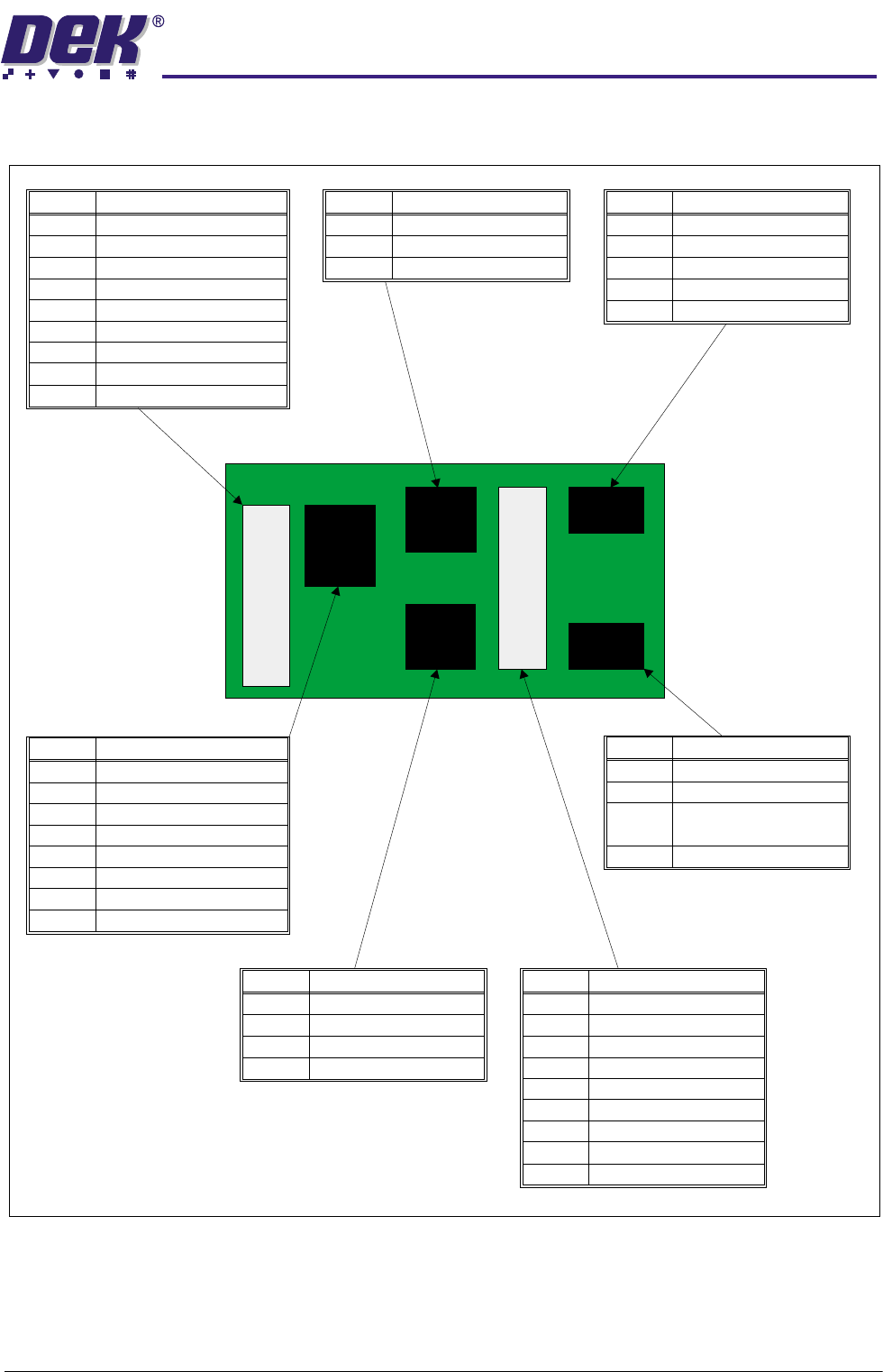
Breakout Board A
Pin No.
1
2
6-13
4
3
15
17
14
18-25
X Rear Fine Home
X Forward Coarse Home
Y Actuator Coarse Home
Camera Y Home
Y Actuator Fine Home
+12V
X Rear Coarse Home
0V
X Forward Fine Home
Signal
Pin No.
1
2
6-13
4
3
15
16
14
18-25
Rising Table Home
Rail Lifted Left
Camera X Home
Print Carriage Home
Rail Lifted Right
+12V
Rising Table Limit
0V
Rising Table Interlock
Signal
Pin No.
1
2
3
+12V
Camera X Home
0V
Signal
Pin No.
1,4,7
2
3,6,9
5
8
+12V
Rising Table Home
0V
Rising Table Limit
Rising Table Interlock
Signal
Pin No.
1,4
2
3,6
5
+12V
Print Carriage Home
0V
Camera Y Home
Signal
Pin No.
1,4,7,10
2
3,6,8,
9,11,12
5
+12V
Rail Lifted Left
0V
Rail Lifted Right
Signal
Pin No.
1,5,9
2
6
4,8,12
3
10
11
7
+12V
0V
Y Actuator Fine Home
Y Actuator Coarse Home
X Forward Coarse Home
X Rear Fine Home
X Forward Fine Home
X Rear Coarse Home
Signal
APL2
APL1
ASK7
ASK5
ASK6
ASK3
ASK4