Printer 600 Machine Controller.pdf - 第35页
0$&+ ,1(&21752 //(5 '8$/67( 33(5'5,9( Chapter Issue 4 May 03 Technical Reference Manual 6.35 S tepper Drive Card Figure 6-25 Dual S t epper Drive PCB F use F1 - 0.5A T F use F2- 3.15A T +5V Regulator…
0$&+,1(&21752//(5
'8$/67(33(5'5,9(
6.34 Technical Reference Manual Chapter Issue 4 May 03
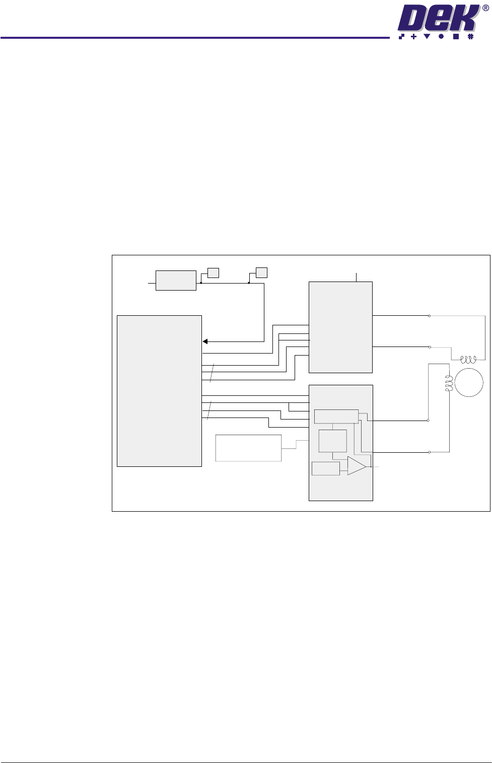
Output Signals Each micro controller is preprogrammed with a machine code that utilizes the
direction and step data from the multiplexer (MUX Dir/Step), to sequence the
stepper drive signals (RB0-7). These signals are fed to two LMD 18245 devices.
The LMD devices each form a bi-polar chopper amplifier stage providing single
phase drive to one half of the stepper motor (CHxA+ and CHxA-) or (CHxB+
and CHxB-) windings. Outputs RB0 and RB4 provide the direction data and are
utilized in the chopper circuit to switch the H-Bridge power switches and hence
the current direction in the phase winding. The LMD device compares the DAC
reference voltage mentioned previously with the output of the current sense
amplifier this is connected to the jumper links - JP3, 4, 5, 6, 9, 10, 11 and 12.
The links are all factory set to achieve either half step 1A/phase or half step 2A/
phase outputs. The actuators and the paste dispense stepper motors are rated
at 1A/phase. The squeegee motors, the moving rail motors are rated at 2A/
phase.
Figure 6-24 Dual Stepper Block Diagram
Microcontroller
RA0-RA1
Dir
Dir
RB0
RB1/2/3
RB4
RB5/6/7
{
{
CHxA+
24VSW
Rotor
CHxB+
CHxA-
CHxB-
TP1
or TP3
TP2
or TP4
+5V Reference
Voltage
H-Bridge
Chopper
Amplifier
H-Bridge
Stepper
Motor
NOTE
Both halves are identical.
LMD 18245
LMD 18245
PIC16C54
DAC
I
Sense
I/P Buffer
Step/Dir
0$&+,1(&21752//(5
'8$/67(33(5'5,9(
Chapter Issue 4 May 03 Technical Reference Manual 6.35
Stepper Drive Card
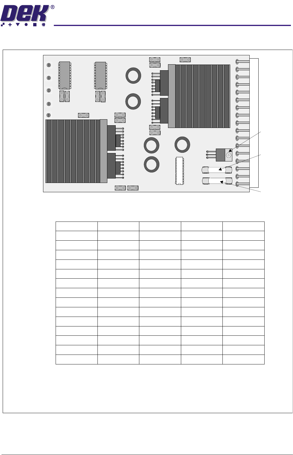
Figure 6-25 Dual Stepper Drive PCB
Fuse F1 -
0.5AT
Fuse F2-
3.15AT
+5V
Regulator
TP4 - Step 2
TP5-0V
TP2 - Step 1
TP3 - Dir 2
TP1 - Dir 1
JP11
JP3
JP4
JP9
JP10
JP5
JP1
JP2
JP7
JP8
JP6
JP14
JP12
JP13
Jumper Links
Slot X3
Slot X4
Slot X5
Slot X6
X
X
X
X
X
X
X
X
X
X
X
X
JP1
JP2
JP3
JP4
JP5
JP6
JP7
JP8
JP9
JP10
JP11
JP12
JP13
JP14
Dual Stepper Card Configuration Table
NOTE
denotes jumper link fitted.
X
CAUTION
ANTI STATIC HANDLING. Standard precautions must be adhered to when handling
electronic cards and configuring and inserting cards into enclosures.
0$&+,1(&21752//(5
'8$/67(33(5'5,9(
6.36 Technical Reference Manual Chapter Issue 4 May 03
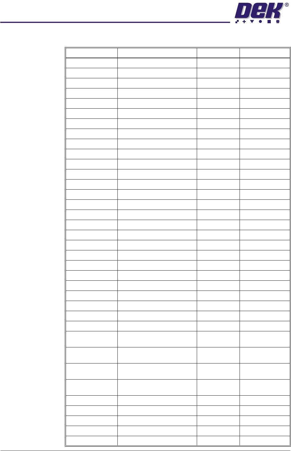
Stepper Drive Designations
Signal Function Destination Source
Motor 2A- Front Squeegee Stepper Motor 9M3 Stepper Drive X5
Motor 2A+ Front Squeegee Stepper Motor
Motor 2B- Front Squeegee Stepper Motor
Motor 2B+ Front Squeegee Stepper Motor
Front Sq. Home Switch - Home PCB E - ESK4 MUX PL1
Motor 1A+ Rear Squeegee Stepper Motor 9M4 Stepper Drive X4
Motor 1A- Rear Squeegee Stepper Motor
Motor 1B+ Rear Squeegee Stepper Motor
Motor 1B- Rear Squeegee Stepper Motor
Rear Sq. Home Switch - Home PCB E - ESK4 MUX PL1
Motor 1B- Y Actuator Stepper Motor Stepper Drive X5
Motor 1B+ Y Actuator Stepper Motor
Motor 1A- Y Actuator Stepper Motor
Motor 1A+ Y Actuator Stepper Motor
Y Actuator Home Switch - Home Coarse 9PL35 M19SK09
Y Actuator Home Switch - Home Fine
Motor 2A- Moving Rail Stepper Motor 8M2 Stepper Drive X4
Motor 2A+ Moving Rail Stepper Motor
Motor 2B+ Moving Rail Stepper Motor
Motor 2B- Moving Rail Stepper Motor
Mov. Rail Home Switch - Moving Rail Home 8SE6 MUX PL1
Motor 2B- X Rear Actuator Stepper Motor Stepper Drive X3
Motor 2B+ X Rear Actuator Stepper Motor
Motor 2A- X Rear Actuator Stepper Motor
Motor 2A+ X Rear Actuator Stepper Motor
X Rear Act. Home Switch - Home Coarse 9PL34 M19SK09
X Rear Act. Home Switch - Home Fine 9PL34 M19SK09
Motor 1B+ X Forward Actuator Stepper
Motor
Stepper Drive X3
Motor 1B- X Forward Actuator Stepper
Motor
Motor 1A- X Forward Actuator Stepper
Motor
Motor 1A+ X Forward Actuator Stepper
Motor
X Fwd. Act. Home Switch - Home Coarse 9PL33 M19SK09
X Fwd. Act. Home Switch - Home Fine 9PL35 M19SK09
Motor 1B+ Paste Dispenser Motor Stepper Drive X6
Motor 1B- Paste Dispenser Motor
Motor 1A- Paste Dispenser Motor