Printer 600 Machine Controller.pdf - 第18页
0$&+,1( &21752//( 5 &$1%86 6.18 Technical Reference Manual Chapter Issue 4 May 03 CAN BUS The Controll er Area Network ( CAN) is a bus syst em for machine motion cont rol. A transcei ver for the 1 Mbaud rat…
0$&+,1(&21752//(5
1(;7029(&$5'
Chapter Issue 4 May 03 Technical Reference Manual 6.17
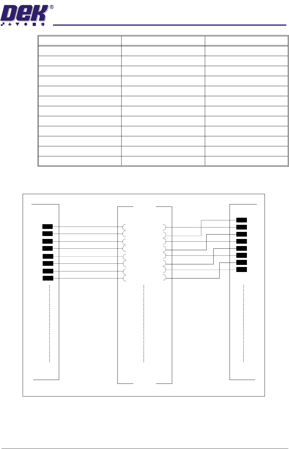
Figure 6-12 Sample of Next Move Breakout Wiring
PIN 39 DIG.IN.7 PIN 77 ¦ PIN 78 PIN 40 DIG.IN.8
PIN 40 DIG.IN.9 PIN 79 ¦ PIN 80 PIN 39 DIG.IN.10
PIN 41 DIG.IN.11 PIN 81 ¦ PIN 82 PIN 42 DIG.IN.12
PIN 42 DIG.IN.13 PIN 83 ¦ PIN 84 PIN 41 DIG.IN.14
PIN 43 DIG.IN.15 PIN 85 ¦ PIN 86 PIN 44 DIG.IN.16
PIN 44 DIG.IN.17 PIN 87 ¦ PIN 88 PIN 43 DIG.IN.18
PIN 45 DIG.IN.19 PIN 89 ¦ PIN 90 PIN 46 DIG.IN.20
PIN 46 DIG.IN.21 PIN 91 ¦ PIN 92 PIN 45 DIG.IN.22
PIN 47 DIG.IN.23 PIN 93 ¦ PIN 94 PIN 48 GND
PIN 48 +5V O/P PIN 95 ¦ PIN 96 PIN 47 GND
PIN 49 +5V O/P PIN 97 ¦ PIN 98 PIN 50 RELAY COM
PIN 50 RELAY N/C PIN 99 ¦ PIN 100 PIN 49 RELAY NO
Connector M19PL15 Connector M19SK16 Connector M19PL17
01
M19SK16
M19PL17
M19PL15
Refer to Drawing 155502 Sh 01 for detail
01
50 50
100
99
0102
0$&+,1(&21752//(5
&$1%86
6.18 Technical Reference Manual Chapter Issue 4 May 03
CAN BUS The Controller Area Network (CAN) is a bus system for machine motion control.
A transceiver for the 1Mbaud rate CAN serial link is fitted to the NextMove card
to enable communication with the two MultiMove cards. The CAN is a 2-wire
data link designed for transmission of small data packets for fast update of axis
position information.
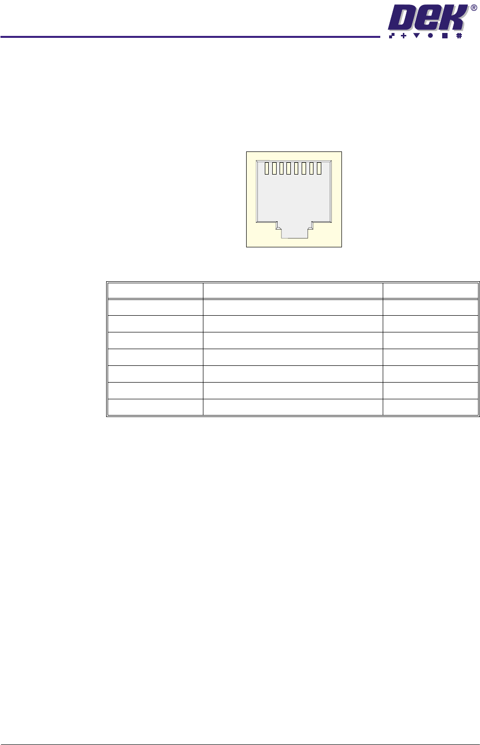
The CAN is presented on two shielded RJ - 45 sockets.
Figure 6-13 CAN Bus Connector
Signal Function RJ-45 Pin
CAN+ CAN Data Signal 1
CAN- CAN Data Signal 2
CAN V+ Power to the CAN Nodes 5
GND Chassis Connection 4
Chassis Screen Pin
N/C No Connection 3,6,7,8
Chassis 360 Degree Cable Screen Shell
1
8
0$&+,1(&21752//(5
08/7,029(
Chapter Issue 4 May 03 Technical Reference Manual 6.19
MULTIMOVE Two MultiMove cards fitted in slots X12 and X13, control the outputs and inputs
for the upline and downline machine interface (MIU), data collection from and
to machine sensors and provide drive to the 24V motors, screen clamps, air
valves and solenoid devices. The cards are controlled by the Controller Area
Network (CAN) with provision for a third card if required. X12 is 24Vdc switched
X13 is 24Vdc unswitched, this card remains on during an emergency stop to
enable control of certain functions eg, board stop and board clamp release etc.
Card Features The MultiMove cards each have the following features:
• Eight 2A source-sink (totem) drivers for PWM control.
• Eight 2A source drivers.Sixteen opto-isolated digital inputs with LED status
indication.
• Sixteen opto-isolated digital inputs with LED status indication.
• Remote operation via a 1Mbit/s serial communication link (CAN BUS).
• Error indication of faults on output circuits.
• Isolation of µ processor circuit from power drivers.
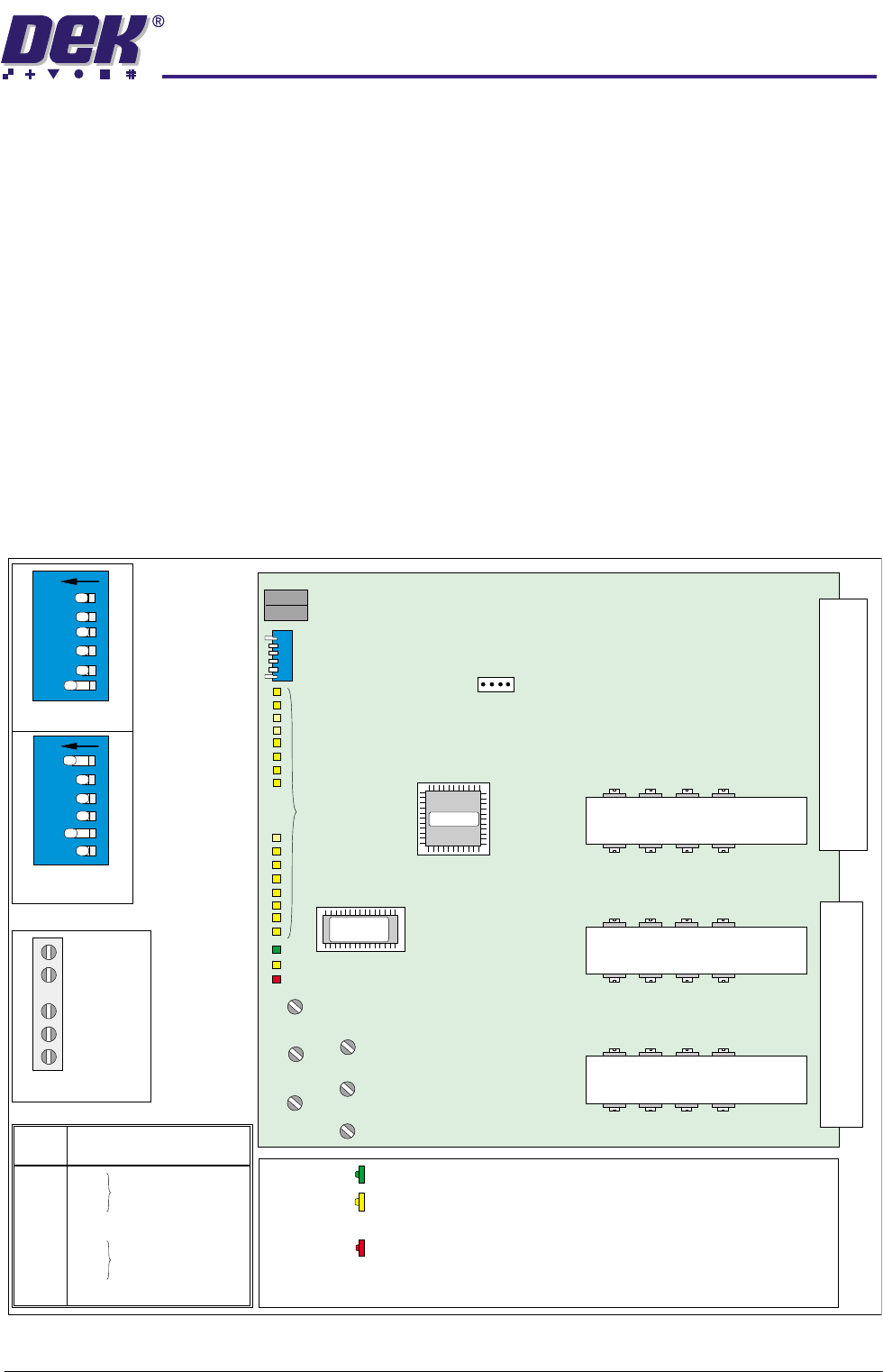
Figure 6-14 MultiMove Card Layout
LED
Indications
Green LED -
+5V Power is being supplied to the microprocessor.
Yellow LED -
LED lights momentarily to indicate that the
microprocessor is being addressed via the CAN.
Red LED -
LED flashes at 1Hz rate. Communications over the
CAN have failed or an error has been detected on
an output channel.
U219
U217 U223 U221
SOURCE OUTPUT DRIVERS
(ALONG HEAT SINK)
U220 U218
U224 U222
U200 U202 U204 U206
U201 U203
U205
U207
MICROPROCESSOR
(green)
+5V
(red)
ERR
(yellow)
CAN
TPX16
VCC
TPX17
VPOWR
TPX18
VISOL
TOTEM OUTPUT DRIVERS
U208
U210 U212
U214
U209
U211
U213
U215
TOTEM OUTPUT DRIVERS
IN 8
IN 9
IN A
IN B
IN C
IN D
IN E
IN F
DIG I/P STATUS
Yellow LEDs
TPX20
GND
TPX15
SWPWR
TPX19
GNDISOL
EEPROM
IC 10
IC 8
IN 1
IN 2
IN 3
IN 4
IN 5
IN 6
IN 7
IN 0
JP11
Bit Switches
(Note the different
configurations)
RJ - 45 CAN Connectors
MultiMove X13
MultiMove X12
12
3
4
56
ON
12
3
4
56
ON
Microprocessor
Power
Test
Point
Voltage
TPX20
TPX16
TPX17
TPX18
TPX19
TPX15
0V
5V
24V
5V
0V
24V SW
TP 20
TP 16
TP 17
TP 18
TP 19
Early Test Points