Printer 600 Machine Controller.pdf - 第16页
0$&+,1( &21752//( 5 1(;7029( &$5' 6.16 Technical Reference Manual Chapter Issue 4 May 03 NextMove Breakout Input s and Output s Connec tor M19PL 15 Connec tor M19SK1 6 Connecto r M19PL1 7 PIN 1 ANALOG …
0$&+,1(&21752//(5
1(;7029(&$5'
Chapter Issue 4 May 03 Technical Reference Manual 6.15
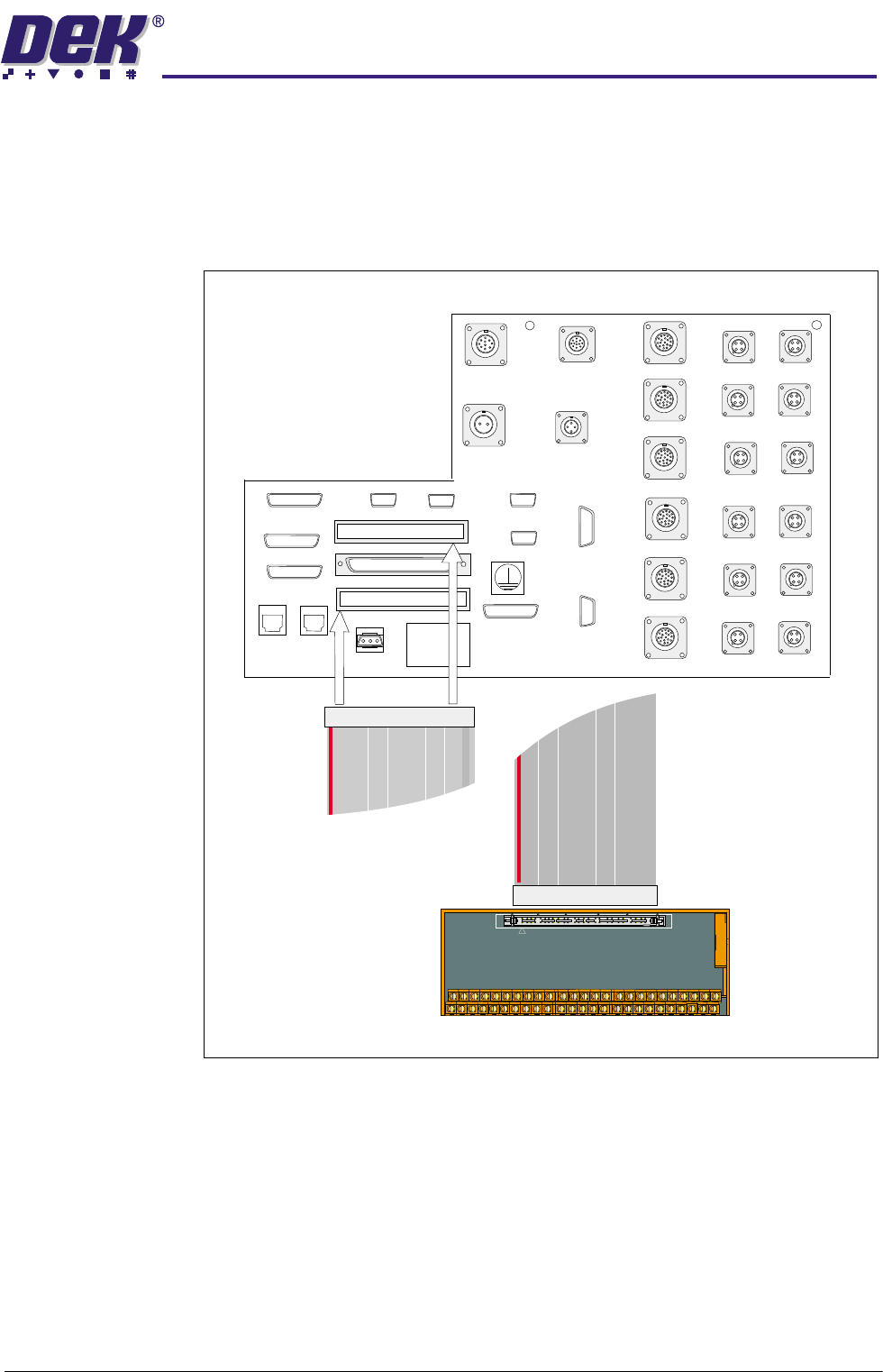
Service Tool The NextMove breakout service tool has screw terminals to enable easy
connection of test equipment to the 50 way breakout connectors M19PL15 and
M19PL17. This tool is used to enable all the signals available on the breakout
board sockets to be accessed for monitoring. Plug M19PL15 connects to all of
the odd numbered pins (1 through to 99) in connector M19SK16 whilst plug
M19PL17 connects to the even numbered pins of M19SK16.
Figure 6-11 NextMove Breakout Service Tool
50 way IDC Connector
50 way IDC Connector
Service Tool
Rear Connector Panel
MODEL
BATCH NO
BATCH
CENTRE
M19SK45
M19SK39
M19SK38
M19SK37
M19SK36
M19SK35
M19SK34
M19SK33
M19SK32
M19SK31
M19SK27
M19SK26
M19SK30
M19SK29
M19SK28
M19PL24
M19SK22
M19SK23
M19SK19
M19SK20
M19SK21
M19SK14
M19SK13
M19SK15
M19SK16
M19SK17
M19SK18
M19SK08
M19SK10
M19SK11
M19SK12
M19SK09
M19SK25
M19SK44
M19SK43
M19SK42
M19SK41
M19SK40
NOTE
To monitor the signals on
the 100 Way NextMove
Connector M19SK16
connect the Service Tool
to either M19PL15 or
M19PL17 using the
interface ribbon cable.
0$&+,1(&21752//(5
1(;7029(&$5'
6.16 Technical Reference Manual Chapter Issue 4 May 03
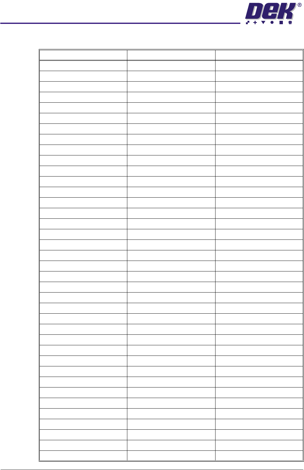
NextMove Breakout Inputs and Outputs
Connector M19PL15 Connector M19SK16 Connector M19PL17
PIN 1 ANALOG GND PIN 1 ¦ PIN 2 PIN 2 ADC0
PIN 2 ADC1 PIN 3 ¦ PIN 4 PIN 1 ADC2
PIN 3 ADC3 PIN 5 ¦ PIN 6 PIN 4 ADC4
PIN 4 ADC5 PIN 7 ¦ PIN 8 PIN 3 ADC6
PIN 5 ADC7 PIN 9 ¦ PIN 10 PIN 6 DAC0
PIN 6 DAC1 PIN 11 ¦ PIN 12 PIN 5 DAC2
PIN 7 DAC3 PIN 13 ¦ PIN 14 PIN 8 ANALOG GND
PIN 8 DOP0 PIN 15 ¦ PIN 16 PIN 7 DOP1
PIN 9 DOP2 PIN 17 ¦ PIN 18 PIN10 DOP3
PIN 10 DOP4 PIN 19 ¦ PIN 20 PIN 9 DOP5
PIN 11 DOP6 PIN 21 ¦ PIN 22 PIN 12 DOP7
PIN 12 DOP8 PIN 23 ¦ PIN 24 PIN 11 DOP9
PIN 13 DOP10 PIN 25 ¦ PIN 26 PIN 14 DOP11
PIN 14 USER V+ PIN 27 ¦ PIN 28 PIN 13 USR GND
PIN 15 CAN WIRE+ PIN 29 ¦ PIN 30 PIN 16 CAN WIRE-
PIN 16 !EXT.INT.U PIN 31 ¦ PIN 32 PIN 15 ENCO.1
PIN 17 ENCO!! PIN 33 ¦ PIN 34 PIN 18 ENCO.B
PIN 18 ENCO!B PIN 35 ¦ PIN 36 PIN 17 ENCO.A
PIN19 ENCO!A PIN 37 ¦ PIN 38 PIN 20 ENC1.1
PIN 20 ENCO1!! PIN 39 ¦ PIN 40 PIN 19 ENC1.B
PIN 21 ENC.1 !B PIN 41 ¦ PIN 42 PIN 22 ENC1.A
PIN 22 ENC1 !A PIN 43 ¦ PIN 44 PIN 21 ENC2.1
PIN 23 ENC2!! PIN 45 ¦ PIN 46 PIN 24 ENC2.B
PIN 24 ENC2 !B PIN 47 ¦ PIN 48 PIN 23 ENC2.A
PIN 25 ENC2 !A PIN 49 ¦ PIN 50 PIN 26 ENC3.1
PIN 26 ENC3!! PIN 51 ¦ PIN 52 PIN 25 ENC3.B
PIN 27 ENC3 !B PIN 53 ¦ PIN 54 PIN 28 ENC3.A
PIN 28 ENC3 !A PIN 55 ¦ PIN 56 PIN 27 USR V+
PIN 29 PULSE 0 PIN 57 ¦ PIN 58 PIN 30 DIR 0
PIN 30 BOOST 0 PIN 59 ¦ PIN 60 PIN 29 PULSE 1
PIN 31 DIR 1 PIN 61 ¦ PIN 62 PIN 32 BOOST 0
PIN 32 PULSE 2 PIN 63 ¦ PIN 64 PIN 31 DIR 2
PIN 33 BOOST 2 PIN 65 ¦ PIN 66 PIN 34 PULSE 3
PIN 34 DIR 3 PIN 67 ¦ PIN 68 PIN BOOST 3
PIN 35 USER GND PIN 69 ¦ PIN 70 PIN 36 DIG.IN.0
PIN 36 DIG.IN.1 PIN 71 ¦ PIN 72 PIN 35 DIG.IN.2
PIN 37 DIG.IN.3 PIN 73 ¦ PIN 74 PIN 38 DIG.IN.4
PIN 38 DIG.IN.5 PIN 75 ¦ PIN 76 PIN 37 DIG.IN.6
0$&+,1(&21752//(5
1(;7029(&$5'
Chapter Issue 4 May 03 Technical Reference Manual 6.17
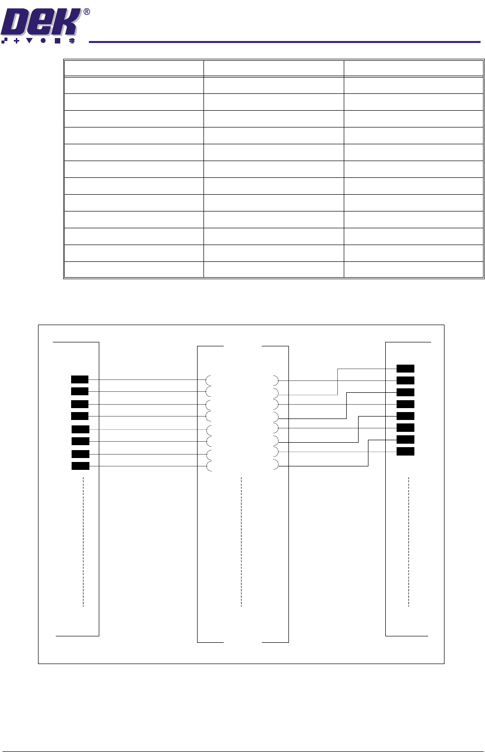
Figure 6-12 Sample of Next Move Breakout Wiring
PIN 39 DIG.IN.7 PIN 77 ¦ PIN 78 PIN 40 DIG.IN.8
PIN 40 DIG.IN.9 PIN 79 ¦ PIN 80 PIN 39 DIG.IN.10
PIN 41 DIG.IN.11 PIN 81 ¦ PIN 82 PIN 42 DIG.IN.12
PIN 42 DIG.IN.13 PIN 83 ¦ PIN 84 PIN 41 DIG.IN.14
PIN 43 DIG.IN.15 PIN 85 ¦ PIN 86 PIN 44 DIG.IN.16
PIN 44 DIG.IN.17 PIN 87 ¦ PIN 88 PIN 43 DIG.IN.18
PIN 45 DIG.IN.19 PIN 89 ¦ PIN 90 PIN 46 DIG.IN.20
PIN 46 DIG.IN.21 PIN 91 ¦ PIN 92 PIN 45 DIG.IN.22
PIN 47 DIG.IN.23 PIN 93 ¦ PIN 94 PIN 48 GND
PIN 48 +5V O/P PIN 95 ¦ PIN 96 PIN 47 GND
PIN 49 +5V O/P PIN 97 ¦ PIN 98 PIN 50 RELAY COM
PIN 50 RELAY N/C PIN 99 ¦ PIN 100 PIN 49 RELAY NO
Connector M19PL15 Connector M19SK16 Connector M19PL17
01
M19SK16
M19PL17
M19PL15
Refer to Drawing 155502 Sh 01 for detail
01
50 50
100
99
0102