Productivity Lift.pdf - 第103页
User Manual - Productivity Lift 12 Reinstallation Edition 02/2004 12.1 Reinstallation 95 12 Reinst allation This chapter explains h ow to reinstall the device. A qua lified person o r employee (service en gi- neer) may o…
11 Fault information User Manual - Productivity Lift
Edition 02/2004
94
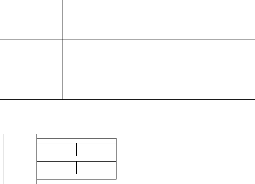
Fig. 11 - 1 Fault information LP blocked
„Fault lift“
Lift drive defective: Timeout, the Lift doesn't arrive one of the defined positions
in this time.
Check the function of the drive and the motor controller.
„Fault Shuttle“
The shuttle movement is faulty.
Check the pneumatic air and position of the sensors.
„Wait for
interface“
The arrived signal is not received following the transfer of a PCB.
Check printed circuit board transfer; PCB may have been jammed during
transfer.
„Fault lift“
„Emergency mode"
The function of the lift brake (clamping cartridge) may have a fault. Please
inform SIEMENS AG L&A.
„Fault shuttle“
„Emergency mode"
The function of the shuttle may have a fault. Please inform SIEMENS AG L&A.
Tab. 11.0 - 1 Fault information
LF
TR1 TR2

User Manual - Productivity Lift 12 Reinstallation
Edition 02/2004 12.1 Reinstallation
95
12 Reinstallation
This chapter explains how to reinstall the device. A qualified person or employee (service engi-
neer) may only do this.
N. B.
For reinstallation, dismantling or disposal the Productivity Lift has to be prepared. For installation
please refer to Installation instruction (Article No.: 00191 967-02).
12.1 Reinstallation
If the Productivity Lift needs to be removed or moved within a production line, please follow
the instructions below.
1. Position the Top Conveyor in its lowest position using the manual mode and install transport
locks (see chapter 2.5 “Fitting the transport locks”).
2. Position Shuttle Conveyor in its lower position and tighten Mount shaft clamp to secure Shuttle
Conveyor.
3. Press the button marked "Stop" on the system control panel.
4. Set the main switch to the "0" position.
5. Disconnect the power supply at the mains cable and store it away as described in the Produc-
tivity Lift installation instructions (chapter „Storing the mains cable“).
6. Disconnect any pneumatic energy supply by removing the feed hose. Pack it sensibly into the
system.
7. Remove any transport goods and magazines intended for this purpose from the device.
8. Remove the keys for the key switch located in the control cabinet to bridge the safety switches
of covers and doors.
9. Close and lock all doors and covers.
12 Reinstallation User Manual - Productivity Lift
12.2 Dismantling Edition 02/2004
96
12.2 Dismantling
Pack and transport the unit after disconnecting, power cords, interface cables and compressed air
lines. Please follow the relevant Safety and Transport regulations during this process.
12.3 Disposal
Only "operators" have responsibility for disposal. They must ensure that the system and its oper-
ating supplies are disposed of correctly.
The construction of the system only involved materials that can be easily recycled or are not harm-
ful when destroyed. Dangerous substances are not necessary for either the construction or oper-
ation of the device.
The relevant national legal provisions must be complied with when disposing of the different de-
vice parts.
12.3.1 Disposing the device
Dispose of the device by taking it apart, sorting the parts separately according to material, and
disposing of them accordingly.
The device consists of the following materials:
Frame : steel
Panelling : steel and plastic
Mechanical components : aluminium
Controller : plastics, non-ferrous metals and electronic components