Productivity Lift.pdf - 第81页
User Manual - Productivity Lift Soko 00166631-01 / 12031477 6 Set-up mode Software version V 43.140 Edition April 2006 6.5 Ramp up mode / Ramp down mode 73 6.5.4 A vailability of Ramp up / Ramp down mode depending on mac…
6 Set-up mode User Manual - Productivity Lift Soko 00166631-01 / 12031477
6.5 Ramp up mode / Ramp down mode Software version V 43.140 Edition April 2006
72
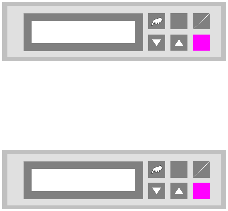
6.5.2 Ramp up mode
PCB distribution parameter, which defines the loading sequence of the PCBs within a cluster of
Siplace units. The value of x depends on the number of Siplace units within a cluster.
The menu allows to set the value x between 0...9.
Fig. 6 - 9 Ramp up mode
6.5.3 Ramp down mode
PCB distribution parameter, which defines the unloading of the PCBs within a cluster of Siplace
units. The value of x depends on the number of Siplace units within a cluster.
The menu allows to set the value x between 0...9.
Fig. 6 - 10 Ramp down mode
ALT
Enter
Start
Stop
Ramp up mode
1 to x
ALT
Enter
Start
Stop
Ramp down mode
1 to x

User Manual - Productivity Lift Soko 00166631-01 / 12031477 6 Set-up mode
Software version V 43.140 Edition April 2006 6.5 Ramp up mode / Ramp down mode
73
6.5.4 Availability of Ramp up / Ramp down mode depending on machine type
The ramp up, ramp down mode depends on the selected machine type as defined in the table be-
low.
6.5.5 Required set-up Ramp-up / Ramp down
For the allowed line configuration with three Single Conveyor Productivity Lifts, and two similar
placement machines following set-up is required:
Lift 1: Input Module, Ramp-up 1:1
Lift 2: Cluster Module, Ramp-up 1:0, Ramp-down 1:0
Lift 3: Output Module, Ramp-down 1:1
6.5.6 Required set-up Ramp-up / Ramp down
For the allowed line configuration with four Single Conveyor Productivity Lifts, and three similar
placement machines following set-up is required:
Lift 1: Input Module, Ramp-up 1:2
Lift 2: Cluster Module, Ramp-up 1:1, Ramp-down 1:0
Lift 3: Cluster Module, Ramp-up 1:0, Ramp-down 1:1
Lift 4: Output Module, Ramp-down 1:2
Input module
Cluster module
Cross module
Convert 2/4
Convert 4/2
Output module
Ramp up mode
X X X
Ramp down mode
X X X
Tab. 6.5 - 1 Availability of Ramp up / Ramp down mode depending on machine type
6 Set-up mode User Manual - Productivity Lift Soko 00166631-01 / 12031477
6.6 Underneath buffer Software version V 43.140 Edition April 2006
74
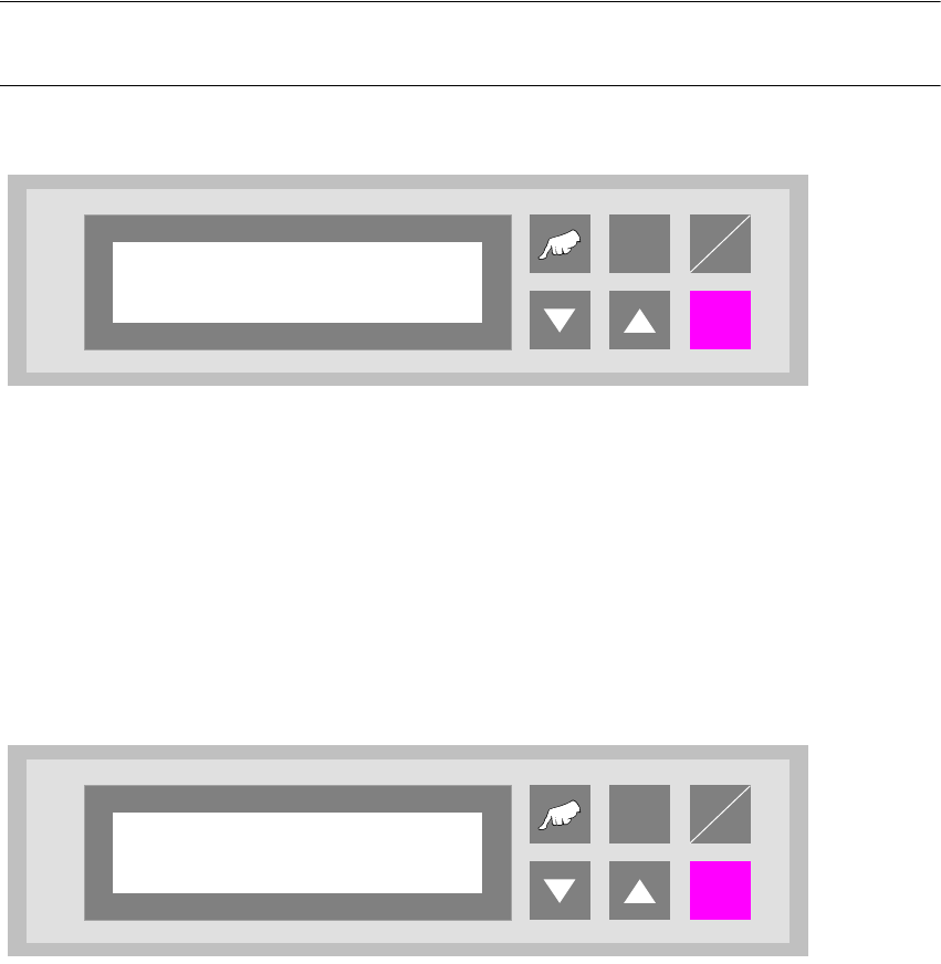
6.6 Underneath buffer
The lower belts can be used as so-called underfloor buffers. This means that if the function is
switched on, two PCBs could be transferred on the belt. As a result, there is an additional further
storage space available for each belt.
NOTE
This menu is not displayed if the underfloor conveyor is switched off (see 5.8).
Fig. 6 - 11 Underneath buffer
6.7 Pass through
If this function is turned on, PCBs are only taken at the upper inlet track 1 or 2 and only delivered
again at the corresponding upper outlet. This is implemented by the additional top conveyor mod-
ule, which is lowered pneumatically to the transport level. This also serves to turn off the shuttle.
Fig. 6 - 12 Pass through
ALT
Enter
Start
Stop
Underneath buffer
Turned off
ALT
Enter
Start
Stop
Pass through
Turned off