Productivity Lift.pdf - 第76页
6 Set-up mode User Manual - Productivity Lift Soko 00166631-01 / 12031477 6.4 Run mode Software version V 43.140 Edition April 2006 68 Output module : The final module is defined as the last lift in the direction of tran…
User Manual - Productivity Lift Soko 00166631-01 / 12031477 6 Set-up mode
Software version V 43.140 Edition April 2006 6.3 Machine type
67
6.3 Machine type
Here, the type of system is determined, which corresponds to the position and mode of operation
of the device thus required in the production line.
The following types of machine are defined for the „Productivity Lift”:
Input module : If the lift is at the beginning of the Siplace assembly line, this setting must be
selected in machine type. The input module can only transfer printed circuit
boards on transport track 1 and 2. Priority is given to attempting to then trans-
fer the PCBs to the placement machine. If this is not possible, the unassem-
bled PCBs are forwarded essentially to track 3 and 4 on the lower level and
then transported for the time being to the next lift (intermediate module) or
the placement machine.
Cluster module : The intermediate module is located after the input module and is defined as
the intermediate module as long as the subsequent placement machines are
of the same type. The intermediate module accepts assembled PCBs from
inlet 1 and 2 and transfers them further to outlet 3 and 4. It accepts unassem-
bled PCBs from inlet 3 and 4 attempts to deposit them at the following place-
ment machine
Allocation of the inlets and outlets to each other:
take-over inlet track 1 and 2 → hand-over outlet track 3 and 4
take-over inlet track 3 and 4 → hand-over outlet track 1 and 2
Cross module : The setting „cross module” must always be selected if the type of placement
machine changes in the line. The cross module handles all incoming PCBs
as if they are unassembled. In this way, the PCBs arriving on tracks 1, 3 are
presented to the placement machine for processing. If the following place-
ment machine is of the same type, PCBs can also be transferred on track 3
at the cross module if the current placement machine is occupied. If the cross
module is the last lift before the final module, no PCBs may be transferred on
track 3. Similarly, no PCBs may be accepted from the last intermediate mod-
ule before this cross module.
6 Set-up mode User Manual - Productivity Lift Soko 00166631-01 / 12031477
6.4 Run mode Software version V 43.140 Edition April 2006
68
Output module : The final module is defined as the last lift in the direction of transit, after the
Siplace systems. Essentially, the final module has no lower belt. If the lift is
implemented as the final module, the above mentioned system types can not
be selected. The PCBs are transferred from tracks 1, 2. The printed circuit
boards can only be delivered at the final module via outlet tracks 1 and 2. No
PCBs can be transferred from track 3 and 4 or transported further on this
tracks.
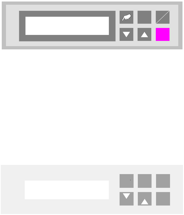
Fig. 6 - 4 Machine type
6.4 Run mode
This function is used to select the operation modes „Pass through“ or „Bypass“.
The operation modes are defined as follows:
6.4.1 Pass through
Incoming PCBs are transferred continuously to the next free machine. This is the normally run
mode
Fig. 6 - 5 Run mode - pass through
ALT
Enter
Start
Stop
Machine type
Input module
ALT
Enter
Hand
Start
Stop
Run mode
Pass through

User Manual - Productivity Lift Soko 00166631-01 / 12031477 6 Set-up mode
Software version V 43.140 Edition April 2006 6.4 Run mode
69
6.4.2 Bypass
Incoming PCBs are bypassing the bonder machines. They are transported only on the underneath
conveyor from the input module to the output module.
All SPL units have to be switched into the bypass mode.
Fig. 6 - 6 Run mode - Bypass
ALT
Enter
Hand
Start
Stop
Run mode
Bypass