Productivity Lift.pdf - 第82页
6 Set-up mode User Manual - Productivity Lift Soko 00166631-01 / 12031477 6.6 Underneath buffer Software version V 43.140 Edition April 2006 74 6.6 Underneath buffer The lower belts can be used as so-called under floor b…

User Manual - Productivity Lift Soko 00166631-01 / 12031477 6 Set-up mode
Software version V 43.140 Edition April 2006 6.5 Ramp up mode / Ramp down mode
73
6.5.4 Availability of Ramp up / Ramp down mode depending on machine type
The ramp up, ramp down mode depends on the selected machine type as defined in the table be-
low.
6.5.5 Required set-up Ramp-up / Ramp down
For the allowed line configuration with three Single Conveyor Productivity Lifts, and two similar
placement machines following set-up is required:
Lift 1: Input Module, Ramp-up 1:1
Lift 2: Cluster Module, Ramp-up 1:0, Ramp-down 1:0
Lift 3: Output Module, Ramp-down 1:1
6.5.6 Required set-up Ramp-up / Ramp down
For the allowed line configuration with four Single Conveyor Productivity Lifts, and three similar
placement machines following set-up is required:
Lift 1: Input Module, Ramp-up 1:2
Lift 2: Cluster Module, Ramp-up 1:1, Ramp-down 1:0
Lift 3: Cluster Module, Ramp-up 1:0, Ramp-down 1:1
Lift 4: Output Module, Ramp-down 1:2
Input module
Cluster module
Cross module
Convert 2/4
Convert 4/2
Output module
Ramp up mode
X X X
Ramp down mode
X X X
Tab. 6.5 - 1 Availability of Ramp up / Ramp down mode depending on machine type
6 Set-up mode User Manual - Productivity Lift Soko 00166631-01 / 12031477
6.6 Underneath buffer Software version V 43.140 Edition April 2006
74
6.6 Underneath buffer
The lower belts can be used as so-called underfloor buffers. This means that if the function is
switched on, two PCBs could be transferred on the belt. As a result, there is an additional further
storage space available for each belt.
NOTE
This menu is not displayed if the underfloor conveyor is switched off (see 5.8).
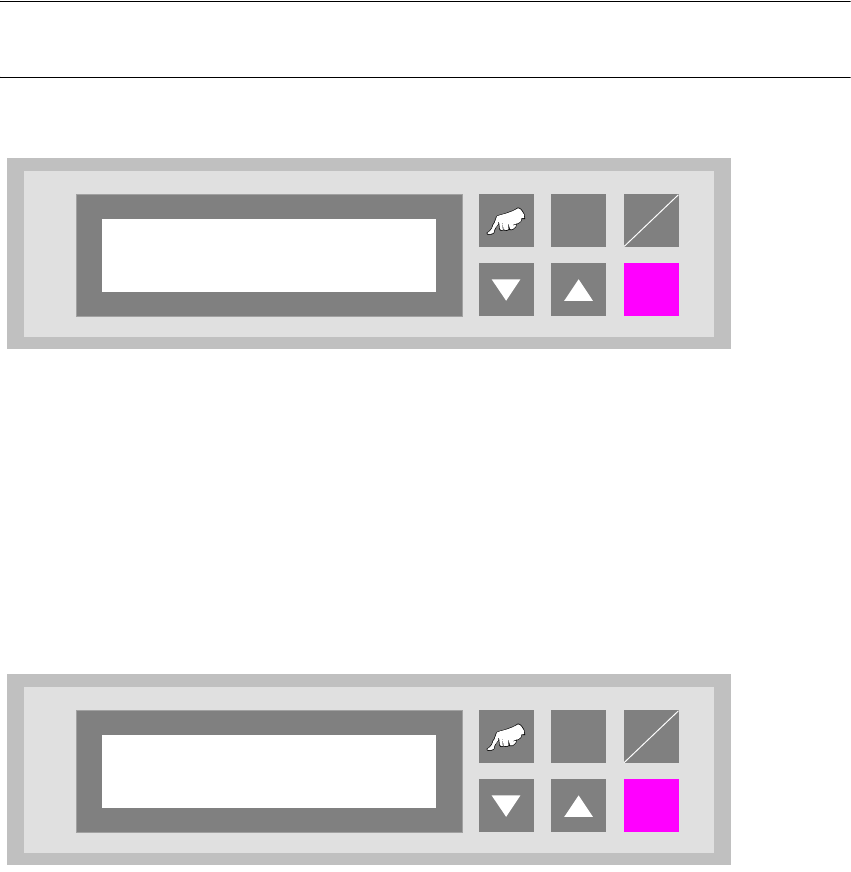
Fig. 6 - 11 Underneath buffer
6.7 Pass through
If this function is turned on, PCBs are only taken at the upper inlet track 1 or 2 and only delivered
again at the corresponding upper outlet. This is implemented by the additional top conveyor mod-
ule, which is lowered pneumatically to the transport level. This also serves to turn off the shuttle.
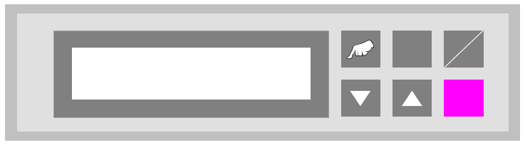
Fig. 6 - 12 Pass through
ALT
Enter
Start
Stop
Underneath buffer
Turned off
ALT
Enter
Start
Stop
Pass through
Turned off
User Manual - Productivity Lift Soko 00166631-01 / 12031477 6 Set-up mode
Software version V 43.140 Edition April 2006 6.8 PCB take over / PCB hand over
75
6.8 PCB take over / PCB hand over
With these set up possibilities it is for example possible to take a feeder out of the line, if the PCB
handover at the first lift and the PCB takeover on the second lift are switched off. The PCBs will
now only be transferred over the lower conveyor to the next lift.
6.8.1 PCB take over
The set up possibilities for the take over of PCBs at the inlet of the upper transport level. The fol-
lowing settings are possible:
Track 1 : PCBs are only taken over on track 1 of inlet 1.
Track 2 : PCBs are only taken over on track 2 of inlet 1.
Double track : PCBs are taken over on both tracks of inlet 1.
Fig. 6 - 13 PCB take over
ALT
Enter
Start
Stop
PCB take over
Double track