Productivity Lift.pdf - 第74页
6 Set-up mode User Manual - Productivity Lift Soko 00166631-01 / 12031477 6.1 Identity number Software version V 43.140 Edition April 2006 66 6.1 Identity number This selection can be used to assign an identific ation nu…
User Manual - Productivity Lift Soko 00166631-01 / 12031477 6 Set-up mode
Software version V 43.140 Edition April 2006
65
6 Set-up mode
In set-up mode, it is possible to enter and modify parameters that do not serve the basic setting
of the system, but that, for example, show the values dependent on the size of the machine type.
Press the „ALT” key to access the „set-up mode” menu.
Definition:
View of the direction of transit.
Fig. 6 - 1 Definition / Schematic of the transport tracks
Spur 2
Track 2
Spur 1
Track 1
Spur 4
Track 4
Spur 3
Track 3
Bedienseite
Operating side
6 Set-up mode User Manual - Productivity Lift Soko 00166631-01 / 12031477
6.1 Identity number Software version V 43.140 Edition April 2006
66
6.1 Identity number
This selection can be used to assign an identification number to the following set of parameters.
When starting the system, only the corresponding PCB number need be called up, and the system
sets the stored parameters automatically. The number consists of two assignment digits and one
eight-digit identification. The assignment digits can be used to call up the parameter set when
starting the system. The eight-digit identification can be changed at random and only serves the
input of user-specific identification numbers. Each number has only one numerical entry.
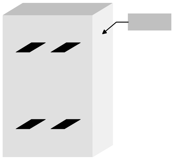
Fig. 6 - 2 Identity number
6.2 Width board
This menu item is only active if the settings „automatic” or „only at start” were selected in the chap-
ter „Width adjusting”.
The value to be entered here can be used to prescribe the transport width of the system numeri-
cally as an absolute value. After starting the automatic operating mode, and after each width ad-
justment reference run, the width prescribed here is automatically reset.
The unit of value is [0.1 mm] in a setting range of 500 to maximum width (corresponds to 50 mm
to maximum width).
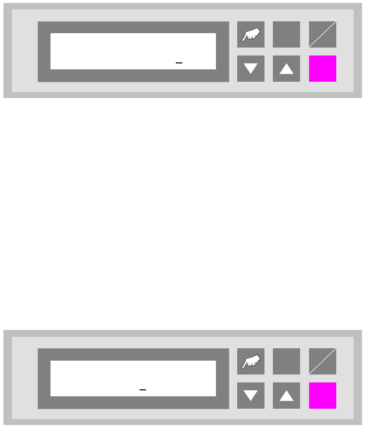
Fig. 6 - 3 Width board
ALT
Enter
Start
Stop
Ident number
01 00000001
ALT
Enter
Start
Stop
Width board
4600
User Manual - Productivity Lift Soko 00166631-01 / 12031477 6 Set-up mode
Software version V 43.140 Edition April 2006 6.3 Machine type
67
6.3 Machine type
Here, the type of system is determined, which corresponds to the position and mode of operation
of the device thus required in the production line.
The following types of machine are defined for the „Productivity Lift”:
Input module : If the lift is at the beginning of the Siplace assembly line, this setting must be
selected in machine type. The input module can only transfer printed circuit
boards on transport track 1 and 2. Priority is given to attempting to then trans-
fer the PCBs to the placement machine. If this is not possible, the unassem-
bled PCBs are forwarded essentially to track 3 and 4 on the lower level and
then transported for the time being to the next lift (intermediate module) or
the placement machine.
Cluster module : The intermediate module is located after the input module and is defined as
the intermediate module as long as the subsequent placement machines are
of the same type. The intermediate module accepts assembled PCBs from
inlet 1 and 2 and transfers them further to outlet 3 and 4. It accepts unassem-
bled PCBs from inlet 3 and 4 attempts to deposit them at the following place-
ment machine
Allocation of the inlets and outlets to each other:
take-over inlet track 1 and 2 → hand-over outlet track 3 and 4
take-over inlet track 3 and 4 → hand-over outlet track 1 and 2
Cross module : The setting „cross module” must always be selected if the type of placement
machine changes in the line. The cross module handles all incoming PCBs
as if they are unassembled. In this way, the PCBs arriving on tracks 1, 3 are
presented to the placement machine for processing. If the following place-
ment machine is of the same type, PCBs can also be transferred on track 3
at the cross module if the current placement machine is occupied. If the cross
module is the last lift before the final module, no PCBs may be transferred on
track 3. Similarly, no PCBs may be accepted from the last intermediate mod-
ule before this cross module.